Various types of security-based projects are already available on bestengineeringprojects.com. Now here is sound operated light and alarm that is used as an intruder alarm, activated when any sound is detected (like the opening of doors, knocking, or door opening) and starts flashing with a sound that alerts you of an intruder. After the second sound pulse is turned off. Circuit Description of Sound Operated Light and Alarm The circuit of sound-operated light and alarm is designed using a pair of timer IC (NE555), a dual JK flip flop IC…
Read MoreCategory: 555 Timer Projects
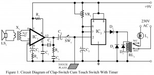
Clap Switch Cum Touch Switch
Various Switching circuits including clap switch, touch witch heat switch is already posted. Now, here is two in one switching circuit i.e. clap switch cum touch switch with a facility of timer. Circuit Description Clap Switch Cum Touch Switch This circuit uses a timer IC NE555 (IC2) and audio amplifier IC TBA810 (IC1). TBA810 is a 7-watt audio amplifier IC which is used to amplify the audio signal coupled from audio transformer X1. Here we used a loudspeaker as a sound sensor. The audio transformer of 3 volts is connected…
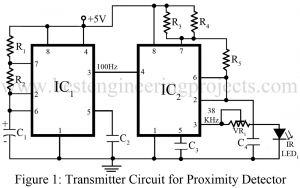
Read MoreProximity Detector Circuit Using 555 timer IC
Entire project of proximity detector circuit is built with infrared transmitter, infrared receiver and 555 timer IC (such as using Seimens SFH50638 in TV sets). Proximity detector circuit, anyone can guess the operation performed by this circuit just with the name it is provided with. Infrared diode is the main soul of proximity detector circuit which is used in different equipment’s like burglar alarms, touch-free proximity switches for turning a light on, and solenoid controlled valves for operating a water tap. Description of Proximity Detector Circuit Using 555 timer IC Transmitter…
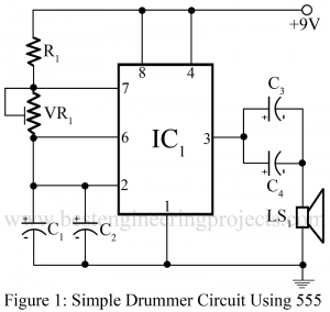
Read MoreSimple Drummer Project Using Timer 555
Timer IC 555 is a low-cost high performance and very popular IC and is used in most circuits. On this website, we have posted various electronic projects using ic 555. Now here, is a simple project called Simple Drummer Project Using Timer 555 which gives an hour of entertainment. Circuit Description of Simple Drummer Project Using Timer 555 The circuit of a simple drummer project is built around NE555 followed by a few passive components. The circuit posted here is simply a triggering circuit whose time is adjusted by variable resistor…
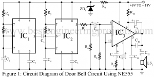
Read MoreDoor Bell Circuit
This project describes the constructional and working details of a door bell circuit. The door bell circuit presented here is of 2-notes (modulated sound) type and delivers about 4-watt Musial power at 12 volt. While using it as a door bell circuit, 6V DC supply is enough, which can be derived either from dry battery cells or a battery eliminator. The door bell circuit is flexible enough to work off right from 6V to 18V supply, without change of any component in the circuitry. However, it is important to use…
Read MoreElectronic Pendulum Using NE555
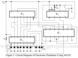
Here is a simple, cheap and vary interesting electronic pendulum. The project electronic pendulum using NE555 can be used in various other gadgets i.e. it can be used in digital clock for pendulum view. Circuit Description of Electronic Pendulum Using NE555: The circuit of electronic pendulum comprises a timer IC NE555 (IC1), CD7400 (IC2), 4-bit up-down counter IC CD74193 (IC3) and a BCD to decimal decoder IC 7442 (IC4). Timer IC NE555 (IC1) is configures in astable multivibrator mode and generate square wave. The frequency of square wave generating from…
Read MoreBeeper Circuit using Timer IC 555
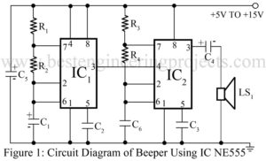
Here is a beeper circuit employing two timer ICs NE555 (IC1 and IC2). The beeper circuit using timer IC NE555 can be used in various circuits that require an alarm or a ‘beeping’ signal. Description of Beeper Circuit Using Timer IC NE555 Timer IC1 is used here in astable mode in such a way that square-wave output at about 1 Hz is obtained. IC2 is also configure in astable mode, but it gives an output with about 1 kHz frequency. The output if IC1 (pin 3) is connected to ‘Reset’…
Read MorePhotoelectric switch using ne555
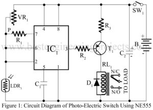
This circuit is of a highly sensitive photoelectric switch using NE555 timer IC. When the LDR1 is kept in light, the switch remains off, but when the light source is removed, the controller circuit gets switched on. This switch has vast application. With little modification, it can be used as a burglar alarm, a corridor visitors monitor, an automatic street lighting system, and as an automatic water tap system. Circuit Description of | Photoelectric switch using NE555 The NE555 timer functions here as a Schmitt trigger. A NE555 IC comprises two…
Read MoreWater Level Controller Using NE555
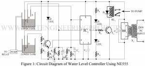
Here is a circuit called Water Level Controller Using 555 which continuously monitors the level in the overhead and ground-level tanks, and switches on the pump whenever the water level in the overhead tanks falls below a predetermined level and switches off the pump whenever it reaches the maximum preset level so that there is no spillage. Further, if the level of water in the lower tank falls below a preset low level, this circuit overrides the commands being sensed from the overhead tank and switches off the pump. This…
Read MoreSequential Timer Circuit Using NE555
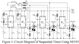
This is a simple sequential timer circuit using NE555 which can be used for psychedelic light, decoration in shops, advertisement boards at night, and parties. The circuit is similar to those published earlier, except for the fact that it incorporates some additional features. Circuit Description Sequential Timer Using NE555 In the circuit sequential timer circuit IC2, IC3 and IC4 are used as monostable multivibrators. The trigger terminals (pins 2) of these ICs are connected in a chain to the previous ICs through an RC differentiator network (0.022 µF capacitor and…
Read More
