Today in this article we are going to build a project called Accident Detection and Alert System using Arduino UNO, GSM module, GPS module, and Vibration Sensor Module. The vibration sensor module used in this project is used to detect the change in linear velocity, displacement, or acceleration. The GPS module detects the exact location (longitude and latitude) and the GSM module is used to send all information to the mobile number assigned in the software code. You may also like the Car Lock System using Arduino and GSM modules.
Introduction of Accident Detection and Alert System using Arduino
The Accident Detection and Alert System using Arduino is very sufficient and worthy to be implemented in the vehicle, especially in developing countries like Nepal, India, Bangladesh, etc. The accident is increasing due to the increase in the number of vehicles, as a result, every year the number of death is increasing. The Accident Detection and Alert System using Arduino prevent uncertain death after an accident because this system sends the message alert to the hospital or police station. The message alert includes longitude, and latitude (location of accident), in the form of a google map link.
Other project-based on GPS posted on bestengineeringprojects.com
- GPS Module Interface with ATmega16
- DIY Distance Measurement using GPS and ATmega328P
- GPS Navigator Circuit using ATmega 16
- GPS and GSM-based Vehicle Tracking System
Working on the Accident Detection and Alert System using Arduino
The working of the project Accident Detection and Alert System using Arduino can be summarized in 3 points below:
- When an accident has occurred, the location details of the vehicle/object are collected by the GPS module from the satellite, this information is in the form of latitude and longitude scales.
- Thus, collected information is then fed to Arduino uno. Necessary processing is done and the information is passed to the LCD and GSM modem.
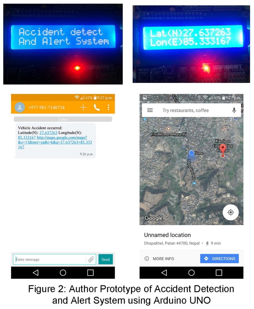
- The GSM modem collects the information for Arduino uno and then transfers it to the mobile phone through the SMS which is in text format.
Parts List of Accident Detection and Alert System using Arduino
- Arduino Uno
- GSM Module (SIM900a)
- GPS Module (SIM28ML)
- Vibration Sensor Module (SW-18010P)
- 16×2 LCD Module
- 10K Variable Resistor
Circuit Description of Accident Detection and Alert System using Arduino
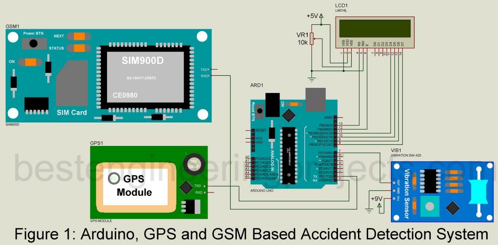
The circuit of the accident detection and alert system is shown in figure 1. This circuit consists of Arduino uno, GSM module, GPS module, vibration sensor module, and LDC module. Now, let’s talk about the component used in this system and circuit connection.
Arduino UNO
It is the central control unit for the project Accident detector and alert system. It gathers information from the vibration sensor module and GPS sensor module, processes it and displays output to LCD, and sends message alerts to the mobile.
GSM Module
SIM900 GSM module is preferred for this project for communication between accident detector and alert system and mobile phone. It is a tri-band that works on various frequency ranges (EGSM 900 MHz, DSC 1800 MHz, and PCS 1900 MHz). To make communication between GSM mobile and Arduino uno, we only used the Rx pin of the GSM module and the Tx pin of the Arduino pin.
GPS Module
SIM28ML GPS module is preferred for this project. The main function of this module is to transmit location data to the Arduino uno. The connection between Arduino uno and GPS module is set by connection to transmit pin Tx of GPS to Arduino uno Rx pin. This module operates in L1 frequency (1575.42 MHz) and up to a fixed territory of about 10 meters in the sky, it generates accurate information. The output of the GPS module is in NMEA format which includes data like location in real-time.
Vibration Sensor Module
SW-18010P vibration sensor module is preferred for this project. As we have already listed the vibration sensor module is designed to analyze linear velocity, displacement, and acceleration. It is a spring-type vibration sensor module thus it detects vibration in any direction.
LCD module
LCD module used in this project is of 16×2 alphanumeric type which is used to display alphabet, numbers, and special characters. LCD interface with an Arduino in 4-bit mode by connecting higher bit data line of LCD (pin 11, 12, 13, and 14) to a digital pin (pin 8, 9 10, and 11) of Arduino as shown in the circuit diagram. Similarly, pin 12 and pin 13 of Arduino are connected to the RS and E pin of LCD. The RW pin of the LCD is grounded to perform a write operating in the LCD.
Software of Accident Detection and Alert System using Arduino
The software is written in Arduino programming language and compiled in Arduino IDK. You can directly download the software code from the link given below. Before using the code change the mobile number.
|
1 2 3 4 5 6 7 8 9 10 11 12 13 14 15 16 17 18 19 20 21 22 23 24 25 26 27 28 29 30 31 32 33 34 35 36 37 38 39 40 41 42 43 44 45 46 47 48 49 50 51 52 53 54 55 56 57 58 59 60 61 62 63 64 65 66 67 68 69 70 71 72 73 74 75 76 77 78 79 80 81 82 83 84 85 86 87 88 89 90 91 92 93 94 95 96 |
#include<LiquidCrystal.h> LiquidCrystal lcd(13,12,11,10,9,8); #define vibrate_sense 7 char str[70]; char *test="$GPGGA"; char logitude[10]; char latitude[10]; int i,j,k; int temp; //int Ctrl+z=26; //for sending msg int led=13; void setup() { lcd.begin(16,2); Serial.begin(4800); pinMode(vibrate_sense, INPUT); pinMode(led, OUTPUT); lcd.setCursor(0,0); lcd.print("Accident Detect"); lcd.setCursor(0,1); lcd.print("Alert System"); delay(3000); } void loop() { if (digitalRead(vibrate_sense)==0) { for(i=18;i<27;i++) //extract latitude from string { latitude[j]=str[i]; j++; } for(i=30;i<40;i++) //extract longitude from string { logitude[k]=str[i]; k++; } lcd.setCursor(0,0); //display latitude and longitude on 16X2 lcd display lcd.print("Lat(N)"); lcd.print(latitude); lcd.setCursor(0,1); lcd.print("Lon(E)"); lcd.print(logitude); delay(100); lcd.clear(); lcd.print("Sending SMS"); Serial.begin(9600); Serial.println("AT+CMGF=1"); //select text mode delay(10); Serial.println("AT+CMGS=\"0123456789\""); // enter receipent number Serial.println("Vehicle Accident occured:"); Serial.print("Latitude(N): "); //enter latitude in msg Serial.println(latitude); //enter latitude value in msg Serial.print("Longitude(E): "); //enter Longitude in Msg Serial.println(logitude); //enter longitude value in msg Serial.print("http://maps.google.com/maps?&z=15&mrt=yp&t=k&q="); Serial.println(latitude); Serial.println("+"); Serial.println(logitude); Serial.write(26); //send msg Ctrl+z=26 lcd.print("SMS Sent"); temp=0; i=0; j=0; k=0; delay(20000); // next reading within 20 seconds Serial.begin(4800); } } void serialEvent() { while (Serial.available()) //Serial incomming data from GPS { char inChar = (char)Serial.read(); str[i]= inChar; //store incomming data from GPS to temparary string str[] i++; if (i < 7) { if(str[i-1] != test[i-1]) //check for right string { i=0; } } if(i >=60) { break; } } } |


As you use vibration sensor if it sense vibration in a small Collision with other vehicle. The message it sent ,without any accident.
can you share me the circuit diagram
Hi, Yatharth.
We had already posted complete circuit, description and code. kindly go through the article.
is there any simulation software for performing this project?
I Can’t unzip your software code
can i use any other gps module?
yes, you can use it with modification in connection or code if required.
where we have to plug remaining rx and tx of gsm and gps modules