Here is the procedure of testing crystal oscillator, oscillator capacitor and oscillator inductor. In a previous article we had posted a circuit called universal crystal oscillator tester for testing crystal oscillator. Now we had posted simple method which is summarize in few point on How to Test Crystal Oscillator below.
An oscillator with a bad crystal may not oscillate at all, may be erratic, or may not oscillate at the correct frequency. One common crystal failure mode is a broken or corroded internal connection. Or if the crystal has been dropped, it may be cracked.
How to Test Crystal Oscillator
Figure 1 shows how to make a simple test to quickly determine the condition of the crystal. Normally, a crystal oscillator will oscillate at a slightly higher frequency than the crystal’s series resonant point. If you can find the series resonant point of the crystal you know the crystal is good.
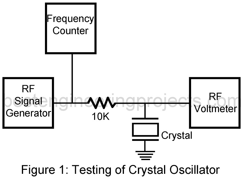
Recall that at the series resonant point, the crystal should have a very low resistance in the order of 100 ohms. At other frequencies, the crystal impedance should be quite high.
The generator should be very carefully tuned across the specified frequency of the crystal. If the crystal is operating properly, the voltmeter will show a dramatic dip at the series resonant point. Remember that the crystal is a very high-Q device, and tuning the signal generator will have to be done very carefully.
Because the impedance of the crystal is very high at the parallel or anti-resonant point, perhaps 50,000 ohms, there should be a peak on the voltmeter at a frequency just slightly above the series resonant point. You should look for the series resonant point first because it is easier to find.
The voltage across a broken crystal will not change much as the generator frequency is varied. Internal connection problems could cause erratic operation. Corrosion problems will cause the resonant frequency to shift from the specified value.
How to Test Oscillator Capacitors
The capacitor associated with the crystal or inductor together with the inductor determine the exact frequency of oscillation. This type of capacitor will seldom show a short, but it can become sensitive to temperature and shock or change value with age.
In the Clapp circuit show in figure 2, C3 is primarily responsible for setting the frequency. While observation the frequency with a counter, cool the capacitor with an aerosol spray sold for cooling electronic equipment. Defective capacitors will generally change value suddenly and shift the frequency a good bit when cooled. If C3 is open the circuit probably will not oscillate at all.
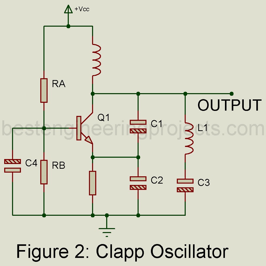
In the Clapp circuit, C1 and C2 are primarily responsible for providing the proper amount of feedback to allow oscillation. If either of these capacitors fails the oscillator fails the oscillator will not work. An oscilloscope connected to the collector of Q1 should show a high-quality sine wave. C1 and C2 do have some effect on the frequency and should not be excluded from suspicion if the frequency is not correct.
How to Test Oscillator Inductors
A shorted or open inductor will completely kill an oscillator. Inductors can be easily checked for an open circuit with an ohmmeter, though the ohmmeter will not detect a shorted turn. A short in the inductor is best detected with a Q-meter or impedance bridge.