Here is a simple circuit “AC Motor Speed Controller Circuit Using Microcontroller” which is used to control the speed of AC motor using microcontroller At89c51. The circuit uses the principle of changing the firing angle of TRIAC to control the speed of the motor. Here, in this project, we had to use various switches to control the speed whereas an LED bar graph is used to indicate the speed of the motor.
Circuit Description of AC Motor Speed Controller Circuit Using AT89C51
The circuit diagram of the signal phase AC motor is divided into three main sections.
- Firing angle control circuit
- Zero crossing detector circuit
- Speed indicating circuit
Firing angle control circuit | AC Motor Speed Controller Circuit Using AT89C51
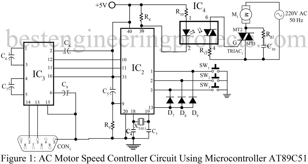
The firing angle control section is shown in figure 1. This section consists of a microcontroller (At89c51) and optocoupler (MUC3011). The optocoupler is used to trigger TRIAC; whereas the microcontroller is used to control the angle and indicating circuit. The output of the zero-crossing detector is given to external interrupt 0 (INT0) pin 12. Pin no.39 is connected to the input of the optocoupler whereas the output is connected to the gate of TRIAC.
The switches SW1, SW2, and SW3 is connected to pin 1, 2, and 3 respectively where diode D9, D8, and D7 are connected as shown in figure 1. Where the function of each switch is shown in Table 1.
| Switches | Functions |
| Switch 1 (SW1) | To switch on/off TRIAC |
| Switch 2 (SW2) | To Increase delay by 1 mS |
| Switch 3 (SW3) | To Decrease delay by 1 mS |
For power-on reset capacitor C5 connected in series with resistor R9 as shown in the circuit diagram.

Zero-Crossing Detector Circuit | AC Motor Speed Controller Circuit Using AT89C51
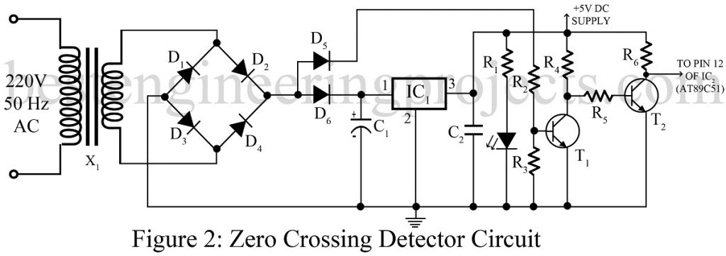
The zero-crossing detector circuit is shown in figure 2. It consists of a voltage regulation section and a zero-crossing section. The input of 220V AC is given to the primary winding of transformer T1 which is stepped down to 9V AC and changed to pulsating DC using a bridge rectifier circuit. One output of the rectifier is given to voltage regulator IC (IC1) through Diode D6. The output of regulator IC is pure 5V DC which is given to the collector of transistors T1 and T2 as biasing voltage.
Similarly, another output of rectifier through diode D5 is given to the base of transistor T1 through the voltage divider circuit comprised of resistors R2 and R3.
The output of transistor T1 is given to the base of transistor T2 where both the transistors act as a switch. The output of transistor T2 is given to pin 12 of IC2.
Indication Circuit | AC Motor Speed Controller Circuit Using AT89C51
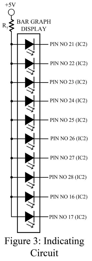
The indicating circuit is shown in figure 3. This circuit consists of a bar-graph display and a current limiting resistor R7. This is used to indicate the condition of the motor as well as the speed of the motor.
The LED connected to pin no 16 of IC2 is to indicate zero-crossing detector circuit status. This blinking LED represents zero crossing detector circuit is working ok.
The LED connected to pin 17 is used to indicate the motor power. When this LED is on its means motor, power enables if LED is off it means power is disabled.
Software:- The source code for a microcontroller is written in C and compiled whereas for the computer it is written in visual basic programming CLICK HERE TO DOWNLOAD THE CODE FOLDER. The folder contains microcontroller code and visual basic code.
Check out other interesting projects using AT89C51 posted in bestengineeringprojects.com
- Frequency Counter Schematic using Microcontroller AT89C51
- Microcontroller AT89C51 based Metro Train Prototype
- DIY Soccer Substitution Board using AT89C51
- Monitoring System using AT89C51
PARTS LIST OF AC MOTOR SPEED CONTROLLER CIRCUIT USING MICROCONTROLLER
| Resistors (all ¼-watt, ± 5% Carbon) |
| R1, R7, R10 = 220 Ω
R2 – R6, R9 = 10 KΩ R8, R11 = 1 KΩ R12 = 100Ω |
| Capacitor |
| C1 = 1000 µF, 25V (Electrolytic Capacitor)
C2 = 1 µF, 25V (Ceramic Disc) C3, C4 = 33 pF (Ceramic Disc) C5 – C9 = 10 µF, 16V (Electrolytic Capacitor) C10 = 0.1 µF (Ceramic Disc) |
| Semiconductors |
| IC1 = LM7805 (5V Series voltage regulator)
IC2 = AT89C51 (Microcontroller) IC3 = MAX232 (Interface IC) IC4 = MOC3011 (random-phase Triac Driver Output Optocoupler) T1, T2 = 2N3904 (NPN bipolar junction transistor) TRIAC1 = BT138 (Series TRIAC) D1 – D9 = 1N4007 (Rectifier Diode) LED1 = 5mm RED LED BAR Graph Display = 10 LED combination |
| Miscellaneous |
| XTAL1 = 12 MHz Crystal oscillator
X1 = 220V AC to 0-9V AC 250 mA step down transformer CON1 = Connector DB9 SW1-SW3 = Push to on Switch |


