There are various types of circuit used to indicate the temperature and humidity of fridge but it cannot measure relative humidity accurately. Because at the time of door opening of fridge relative humidity will rise or fall due to moister of surrounding. Thus, we had posted here “Wireless Temperature and Humidity Indicator for Fridge”.
Here, we had posted a simple, small and handy wireless device which is used to measure temperature, humidity and relative humidity from inside the fridge. The circuit posted here used RF technology to transmit and receive data.
The unit kept inside the fridge used to measure temperature and humidity and transmit data using a 433 MHz RF transmitter unit. Similarly, the receiver kept outside checks the received code and display it on LCD. The output on LCD is real time.
Circuit Description of Wireless Temperature and Humidity Indicator for Fridge using ATmega 328P
The project Wireless Temperature and Humidity Indicator for Fridge using ATmega 328P is divided into two main section i.e. transmitter and receiver section.
Transmitter Section of Wireless Temperature and Humidity Indicator for Fridge
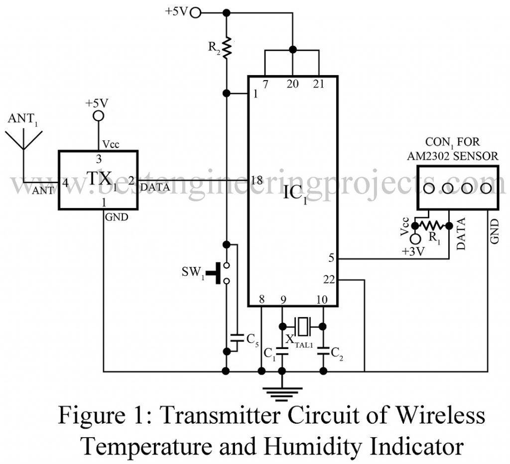
The circuit of transmitter is shown in figure 1 and is built around high-performance 8-bit AVR microcontroller ATmega 328P, an AM2302 and a 433 MHz transmitter module. AM2302 is a wired version of the DHT22 temperature and humidity sensor designed by Adafruit and is connected to connection 1.
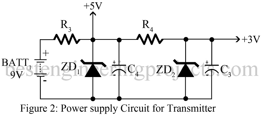
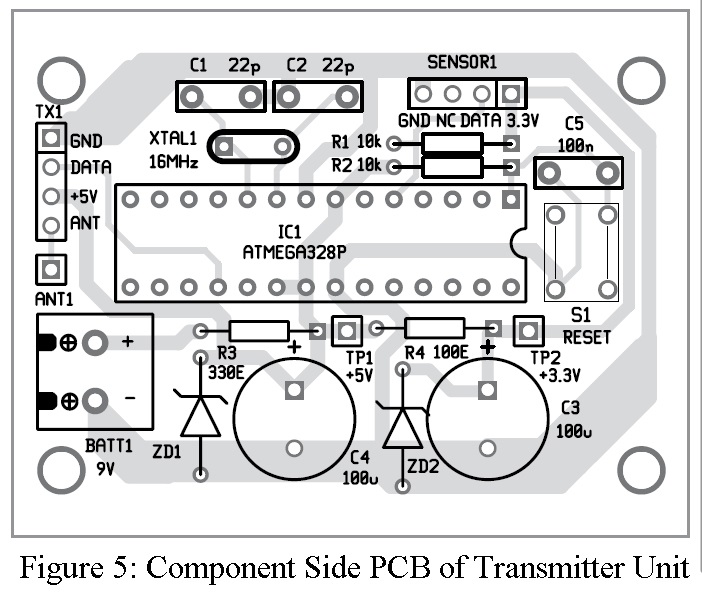
Here, we had used two power supply unit i.e. 5V and 3.3V. A 5V and 3.3V zener diode is used instead of conventual voltage regulator IC because zener diode consume less current in compare to conventual voltage regulator IC. Zener diode ZD1 is of 5 volts where as ZD2 is of 3.3V. Resistors R3 and R4 is current limiting resistor.
Receiver Section Wireless Temperature and Humidity Indicator for Fridge
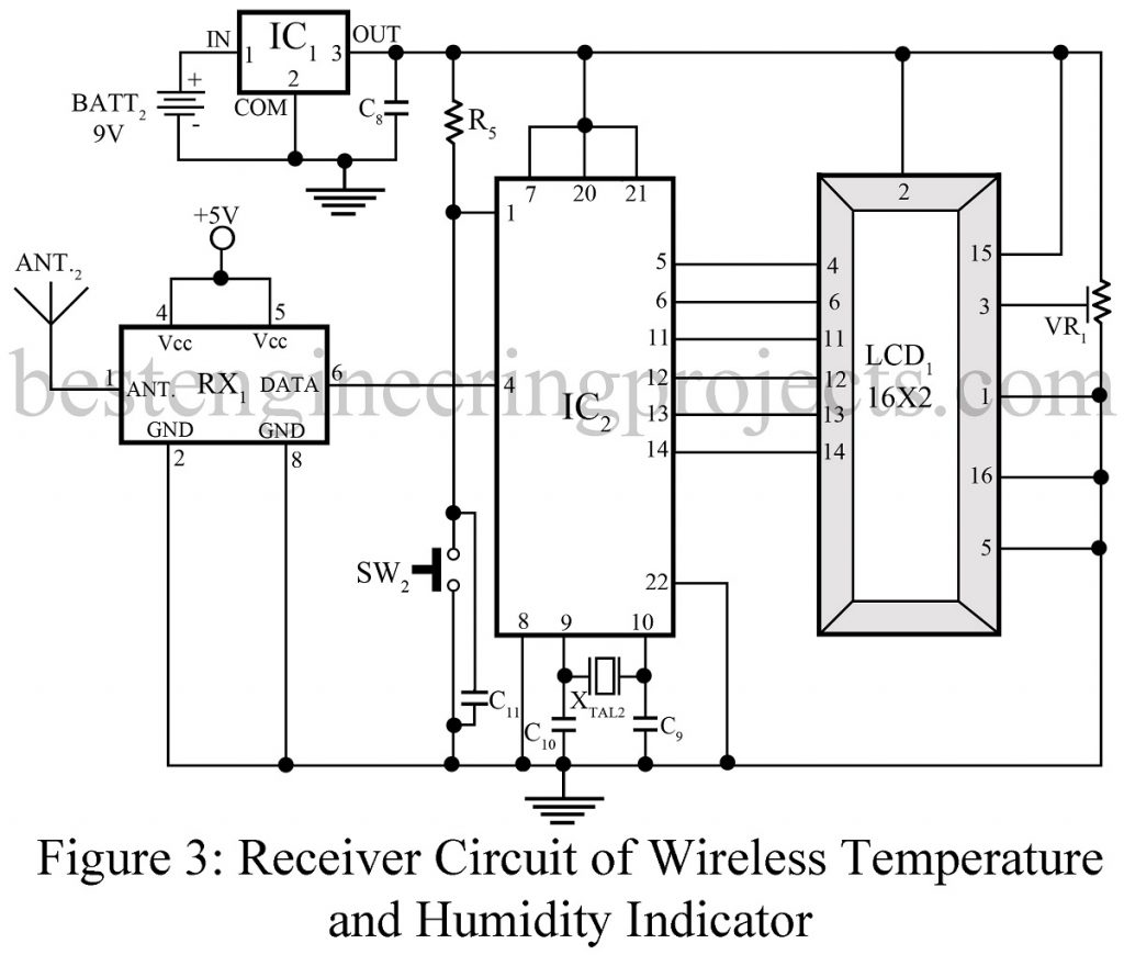
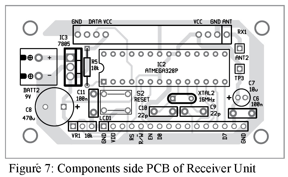
The circuit of receiver is shown in figure 2 and is built around a ATmega 328P, 433 MHz receiver module and LCD. A 5-volt voltage regulator 7805 is used to convert 9V DC to 5V DC. Here we had used voltage regulator IC instead of zener diode because more current is required to drive LCD. The code transmitted by transmitter is received by receiver unit and display the output in LCD in human readable format.
Check out other various interesting project using ATmega328 / Arduino posted in bestengineeringprojects.com
- DIY Distance Measurement using GPS and ATmega328P
- Arduino Based Car Reverse Alarm
- Arduino Gesture Controlled Robot
- Fingerprint Attendance System using Arduino
- Ultrasonic Water Level Meter
Software Code of Wireless Temperature and Humidity Indicator for Fridge
The software code is written in arduino IDE and is burned to ATmega328P using arduino uno. Here two header file is used DHT.h and VirtualWire.h.
DHT.h is used for temperature and humidity sensor
VirtualWire.h is used for 433 MHZ RF transmitter and receiver unit.
Click Here to Download Software Code
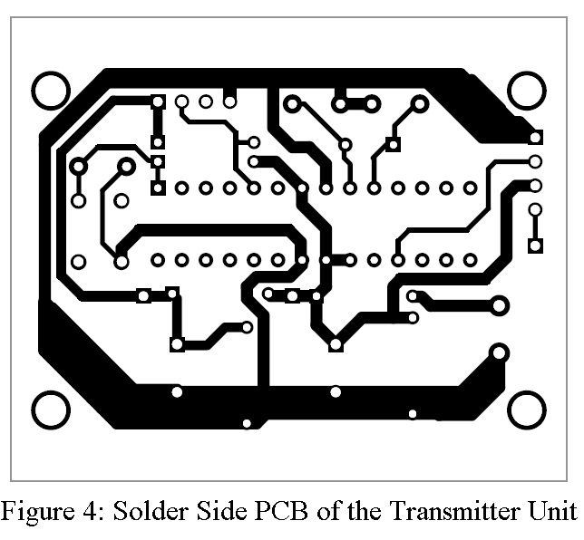
PCB Design of Wireless Temperature and Humidity Indicator for Fridge
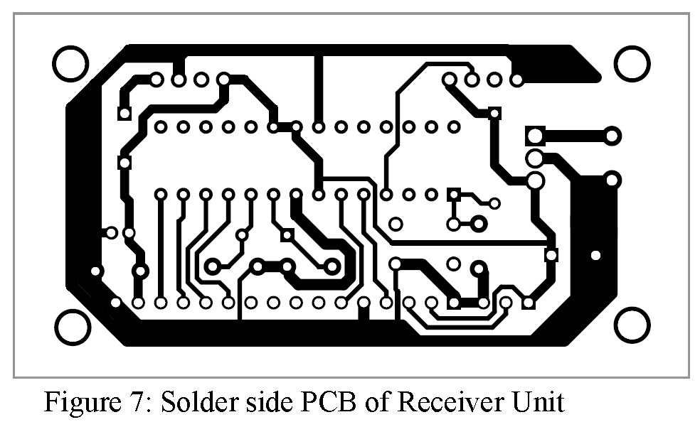
The actual solder side and component side for transmitter and receiver circuit is given below:
Click Here To Download PCB Design
PARTS LIST OF WIRELESS TEMPERATURE AND HUMIDITY INDICATOR FOR FRIDGE
| Resistor (all ¼-watt, ± 5% Carbon) |
| R1, R2, R5 = 10 KΩ
R3 = 330 Ω R4 = 100 Ω VR1 = 10 KΩ |
| Capacitors |
| C1, C2, C9, C10 = 22 pF ceramic disk
C3, C4 = 100 µF/25V electrolytic capacitor C5, C6, C11 = 100 nF ceramic disk C7 = 10 µF/16V electrolytic capacitor C8 = 470 µF/25V electrolytic capacitor |
| Semiconductors |
| IC1, IC2 = ATmega328P MCU with Arduino bootloader
IC3 = 7805 voltage regulator TX1 = 433 MHz RF transmitter module RX1 = 433 MHz RF receiver module ZD1 = 5V zener diode ZD2 = 3.3V zener diode |
| Miscellaneous |
| BATT1, BATT2 = 9V Battery
ANT1, ANT2 = Spiral antenna XTAL1, XTAL2 = 16 MHz crystal oscillator LCD1 = 16*2-character module display SW1, SW2 = Tactile Switch Sensor = AM2302 digital temperature and humidity sensor CON1 = 4-pin connector for sensor |
