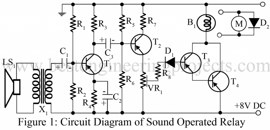
Various type of switching circuit like a touch-operated relay, light operated relay, heat operated relay is already posted in bestengineeringprojects.com. Now here is another simple electronic project in the series of switching circuits called sound-operated relays.
Circuit Description of Sound Operated Relay using Transistors
The circuit of sound operated relay is self-explanatory and is very easy to understand. This circuit is built around a 2-stage audio amplifier using PNP transistors. The sound sensor of the circuit sound-operated relay is done by 8Ω loudspeakers. The output of the loudspeaker is given to the base of the transistor through audio transformer X1 for amplification. The amplified output is given to the input of Darlington pair build around transistors T3 and T4.
As long as the sound wave is present, the Darlington pair remains conductive and the drop across the collector and emitter of the transistor T4 becomes very low i.e. the load is energized. And as the sound wave disappears, the load is de-energized.
Given configuration is for load power up to 2W and for more load power up to 9W the transistor T3 and T4 will be SK100 and BEL AD149.
Check out other sound operated circuits posted in bestengineeringprojects.com
- Sound Operated Intruder Alarm with Flash
- Op-Amp 741 Based Sound Operated Light
- Sound Operated Light and Alarm Circuit
- Sound Operated On-Off Switch
PARTS LIST OF SOUND OPERATED RELAY USING TRANSISTORS
|
Resistor (all ¼-watt, ± 5% Carbon) |
|
R1 = 47 kΩ R2 = 5.6 KΩ R3, R6 = 3.3 KΩ R4 = 820 Ω R5 = 15 KΩ R7 = 220 Ω R8 = 4.7 KΩ VR1 = 250 Ω |
| Capacitors |
| C1, C3 = 10 µF, 12V (Electrolytic Capacitor)
C2 = 33 µF, 12V (Electrolytic Capacitor) |
| Semiconductors |
| T1, T2 = AC126 (General Purposed Germanium Transistor PNP)
T3 = BC158 or SK100 (General Purposed Silicon Transistor NPN) T4 = AC128 or AD149 (General Purposed Germanium Transistor PNP) D1 = OA85 (Germanium Diode) |
| Miscellaneous |
| X1 = Audio transformer or an eliminator transformer
LS1 = 8Ω loudspeaker B1 = 6V Lamp M = Motor |
