In the article Automobile Suspension System Troubleshooting, the major defects that occur in the suspension system of automobiles will be discussed with their possible troubleshooting technique. Rough Ride | Automobile Suspension System Troubleshooting In the conventional rigid axle suspension, the rough ride or the transmission of excessive road shocks to the vehicle body may be due to any or more of the following reasons: The leaves of the spring may be rusted or corroded resulting in excessive friction. The lubrication of the springs should be done immediately to reduce friction. The…
Read MoreAutomobile Steering Troubleshooting
The common faults occurring in the automotive steering systems are discussed below along with Automobile Steering Troubleshooting or remedies technique. Excessive Backlash in Steering | Automobile Steering Troubleshooting The most probable cause of this steering linkage due to wear of ball joints and the steering box. Check these are rectified as required. If the slackness is not present, then the fault may be any of the following. The steering gearbox is loose in the chassis frame which can be tightened. The steering drop arm may be loose on splines. The damaged…
Read MoreWheel and Tyre Troubleshooting
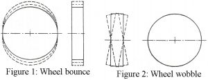
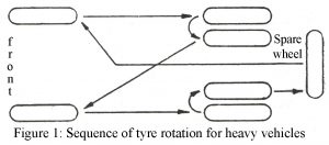
In the article “Wheel and Tyre Troubleshooting” we will discuss the most common troubles occurring on account of wheels and tyres are discussed below, there are altogether thirteen points which we will have to know while troubleshooting wheel and tyre: Wheel bounce or Tramp (Figure 1) The most obvious reason for this is the eccentricity of the wheel and tyre. If on checking, eccentricity is not found, the defect may be due to incorrect tyre pressure, statically unbalanced wheels or statically unbalanced brake drum. To determine which particular wheel is…
Read MorePrecaution Regarding Automobile Tyres
Introduction | Precaution Regarding Automobile Tyres We all know that precaution is better than cure. Here we have compiled a list of precautions regarding automobile tyres. This precaution helps one to know the possible precaution regarding tyres, While fitting tyres onto wheels, ensure the following: The wheel rim is thoroughly cleaned to remove any dirt, grease, rust, etc. and then inspected carefully for cracks. Check the condition of the rim valve hole and make sure that its edges are not damaged, to avoid any damage to the valve. The tube…
Read MoreAutomobile Lighting System Troubleshooting
The following are the main Automobile Lighting System Troubleshooting experienced in the lighting system of an automobile. A few examples of this trouble are given here. Example No light, Dim light, Lamplight but gradually fade out. Here also we had included trends for automotive lighting. No light | Automobile Lighting System Troubleshooting This may be due to the following reasons: Blown-up the fuse. If this is found to be the reason, then before replacement the basic cause of the blowing up (which may be a short-circuit somewhere) must be determined and…
Read MoreElectronic Fuse Using Op-amp 741
Here is an electronic fuse using op-amp 741 which features slow-blow properties, a variable current limit, and a ‘live’ indication of its operation. Moreover, it is simple to restore. The electronic fuse using op-amp 741 allows the gadget to draw a higher current initially but keeps a watch on it. if the gadget continues to draw more current beyond the set time limit, it disconnects the supply. The fuse, therefore, acts as a cut-out and indicates this by a neon glow. It is replaced by simply resetting the circuit once.…
Read MoreBrake Troubleshooting
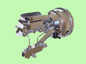
Here in this article, we have mentioned various types of defects that are caused in the braking system of automobiles and brake troubleshooting or remedies for these defects are also given. 1. Loss of braking efficiency | Brake Troubleshooting The brake fluid may have leaked and entered the brake drum and soaked the brake lining. The lining has to be replaced in such a case and the source of the leak repaired. The pressure of air in the system has to be bled. Also, the source of air entry…
Read MoreRFID Based Security System Using Microcontroller AT89C52
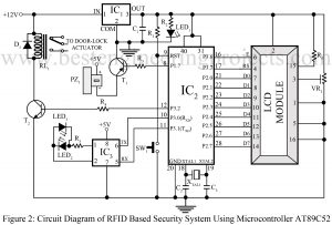
RFID Based Security System Using Microcontroller AT89C52 Different concepts of security systems have flourished along with different techniques and different types of equipment. RFID; Radio-Frequency identification (RFID) is another achievement we are relying on for optimum security facility in multiple projects. It makes use of electromagnetic fields to detect unique tags assigned to objects in the vicinity. There is a reason why it has mustered more popularity in comparison to other security systems that use bar codes and conventional methods. It is because RFID traces tags hidden inside objects, unlike…
Read MoreElectric guitar preamp circuit
The entire circuit of the ‘Electric guitar preamp circuit’ is divided into small sections to ensure simplicity and easy understanding of the project. The first section comprises a single transistor that serves as a common-emitter amplifier. Be it in melodious songs or in rock songs, the guitar is an inseparable part of music in today’s world. To extend the level of sound such that it can be heard by every individual in a mass, amplifier circuits are extensively incorporated into the music system. And this circuit represents a similar concept.…
Read MoreFrequency Counter Schematic using Microcontroller AT89C51
Frequency Counter Schematic using Microcontroller AT89C51 is a simple yet mostly used frequency counter schematic used. The reason behind its simplicity also lies somewhere in the fact that this project uses only two components-AT89C2051 microcontrollers and a 16*2 LCD. Frequency is a crucial subject matter in every project. Precise and accurate frequency generation is another challenge we face in varieties of project design. As per the design of this project, this circuit can withstand frequency ranges between 1 Hz to ~16.5 Mhz, and the rest depends on the characteristics of…
Read More

