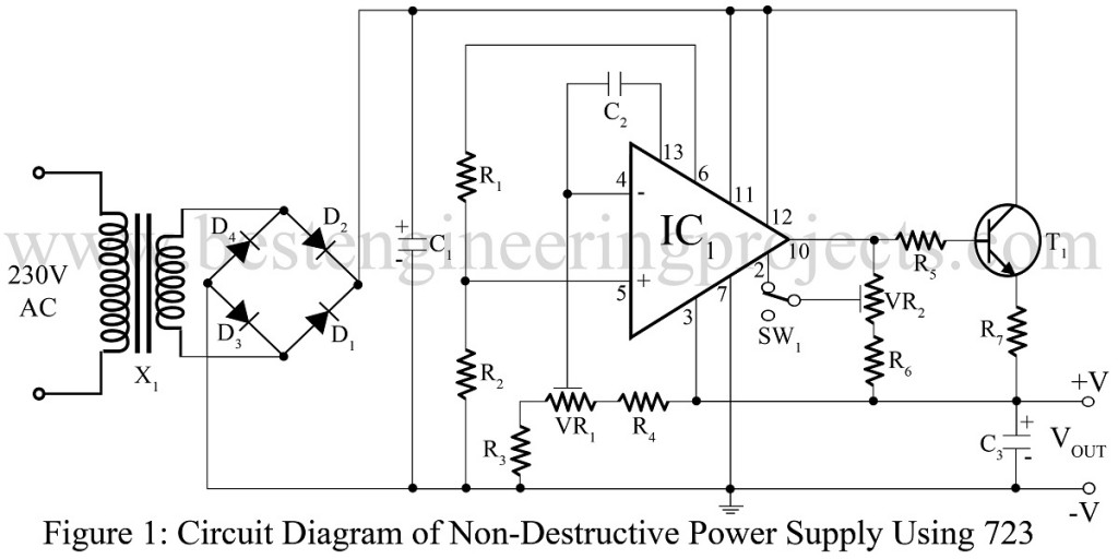
The power supply is the basic unit for any electronic circuit and it must be non-destructive. Various types of power supply circuits like stabilized power supply units, Digital control variable power supply units, self switching off power supply units, etc are available on bestengineeringprojects.com. Now, here is another circuit for smooth power supply in the section of power supply-based projects called a Non-destructive power supply circuit using voltage regulator IC 732.
Working of the circuit non-destructive power supply-Circuit
Most circuits are set to an adjustable “knee” from 2mA to 30mA. The circuit shown here is used to sense the quiescent current ‘knee’ drawn by the circuit. If the value of this current crosses the pre-set value the power of the circuit is automatically withdrawn. The circuit non-destructive power supply circuit provides the regulated voltage for 100mA load with its quiescent range and its output voltage is also adjustable from 4.5V to 9.5V range.
Circuit Description of Non-Destructive Power Supply Circuit
The circuit of the non-destructive power supply is built around a voltage regulator IC (723). Input from AC mains is given to the primary winding of step-down transformer X1 which step-down the voltage to the required level and is rectified using a bridge rectifier comprising diodes D1 through D4. The rectified output is filtered using electrolytic capacitors C1.
The reference voltage at the non-inverting pin (pin 5) is taken from the junction of resistors R1 and R2. A portion of output voltage from the wiper of potentiometer VR1 is fed to the inverting input (pin 4) of the IC.
Potentiometer VR1 is used to set the output voltage. The minimum voltage of 4.5V and maximum voltage of 9.5V at the output from VR1 is set by resistor R3 and R4 which is available across capacitor C3.
The load current is sensed by the resistor R5 and R7. A portion of the voltage drop across R5, R6, and R7 is fed to pin 2 of IC1 through potentiometer VR2. Resistor R6 and potentiometer VR2 are chosen such that at a minimum and maximum position of VR2, the current sensed is of the order of 2mA and 30mA respectively. If the load current exceeds this value of the output, the output voltage becomes almost zero. Thus the knee set is gradually evenly from 2mA to 30mA and the voltage set potentiometer VR1, from 4.5V to 9.5V.
SPDT switch SW1 is used to select the current sensing circuit or voltage regulator circuit. If SW1 disconnects pin 2 of IC1 from the wiper of VR2, thus disabling the current sensing circuit. In this case, the output voltage is regulated at a maximum of 100mA.
Check out other power supply circuit posted in bestengineeringprojects.com
- Adjustable Ripple-Regulated Power Supply Using 741
- Variable Switching Power Supply
- Arduino Controlled Variable Power Supply
- Stabilized Power Supply With Short-Circuit Indication
- Short Proof Variable Power Supply
- Adjustable Bipolar Voltage Regulator Circuit Using LM337
PARTS LIST OF NON-DESTRUCTIVE POWER SUPPLY UNIT
| Resistor (all ¼-watt, ± 5% Carbon) |
| R1 = 5.6 KΩ, 1/2W
R2, R3 = 4.7 KΩ, 1/2W R4 = 3.3 KΩ R5 = 56 Ω R6 = 10 KΩ R7 = 10Ω, 2W VR1, VR2 = 4.7 KΩ, carbon potentiometer |
| Capacitors |
| C1 = 1000 µF, 25V (Electrolytic Capacitor)
C2 = 100 pF, 50V (Ceramic Disc) C3 = 100 µF,12V (Electrolytic Capacitor) |
| Semiconductors |
| IC1 = µA723 (Precision voltage regulator IC)
T1 = 2N1613 or SL100 (Medium power NPN Silicon Transistor) D1 – D4 = 1N4001 (Rectifier Diode) |
| Miscellaneous |
| X1 = 230V/9-10V, 250mA step-down transformer
SW1 = SPDT Switch |
