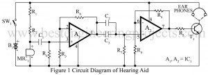
The hearing aid circuit available in the market are fully transistorized and generally use a single pen cell. The hearing aid circuit uses an IC LM358 (IC1) for the same purpose which give better sensitive and performance. You can also check DIY Hearing Aid Circuit using 555. Circuit Description of Hearing Aid Circuit Operational amplifiers are used here in their simplest from non-inverting AC amplifier with a gain of 100. Op-amp A1 forms the first-stage amplifier. Second-stage amplification is given through op-amp A2. Hence the total gain is 10,000. Resistors…
Read MoreCategory: Electronics Projects
Guitar Amplifier | Convert Hawain Guitar to an Electric Guitar
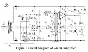
Whereas an electric guitar with 60W PMPO (Peak Music Power Output) costs around $8, here is a cost effective solution to convert a Hawain guitar to an electric guitar. The circuit Guitar Amplifier | Convert Hawain Guitar to an Electric Guitar can also be used as an ampli-speaker with a tape recorder or a radio receiver. Circuit Description of Guitar Amplifier | Convert Hawain Guitar to an Electric Guitar The unit can easily be assembled on a standard TBA810 ampli-speaker PCB available in the market. It is also be housed in…
Read MoreAudio Running Lights Circuit
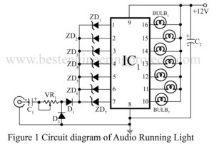
Here is a project for audio running lights circuit which uses filament bulbs instead of LEDs. The circuit employs seven channel darlington array IC ULN2004 and seven reversed biased zener diodes having different breakdown voltages. At low audio level, zener diodes having low breakdown voltages will conduct and corresponding lamps will light up. When output level increases, the other diodes will also conduct. As a result, you can see a very fine display of ‘moving’ light bulbs from top to bottom or from left to right, as per their arrangement.…
Read More100 Rung Exclusive Counter
Digital counters are frequently needed in all kinds of counting circuits, test gear, sequential displays, timers, etc for up to ten outputs (exclusive and independent), or 16 at the most. But the problem arises when it comes to using more than these many outputs. In such a case, the 4017-based CMOS counter can be put to use as a 100-stage counter. The circuit configuration uses a dozen 4017 counter ICs. IC12 sends clock pulses to IC11 at one-tenth of its input frequency, which in turn allows Qa through Qj to…
Read MoreElectronics Fuse Circuit | Electronic Circuit Breaker
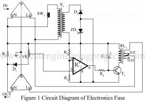
Fuse protection for electronics circuits seems to be an outmoded idea, for there are circuits (in computers etc) that consume high currents initially at a lower stable value. In case high-rated fuses are employed in such equipment to accommodate the initial surge current, it defeats the very purpose of protection. Slow-blow fuses often turn out to be too slow while quick-action fuses may blow out at the mere hint of a surge. An electronics fuse circuit of the kind described here provides an ideal solution in such cases. An electronic…
Read MoreDigital Clock Circuit with Seconds and Alarm Time Display
Most of the digital clock available on the website is only capable to display hour and minute only. Now, here is a project called Digital Clock Circuit with Second and Alarm Time Display which shows not only hour, minute, and second but also alarm time. Best Engineering Projects (BEP) verify the project Digital Clock with Second and Alarm time display with the help of ten 7-segment displays and clock chip mm5387ANN. Circuit Description of Digital Clock Circuit with Seconds and Alarm Timer Display The entire circuit of the Digital Clock…
Read MoreUltrasonic Lamp Brightness Controller Circuit
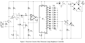
Wireless control of devices using infrared is not new to electronics hobbyists. Now, here is wireless control of the device using ultrasonic sound waves tested in BEP Lab. The project ultrasonic Lamp brightness controller circuit uses ultrasonic sound waves (above 20 kHz) for remote control of lamp brightness. Circuit Description of Ultrasonic Lamp Brightness Controller Circuit As with all wireless control systems, the Ultrasonic lamp-brightness controller comprises a transmitter and receiver circuit. Transmitter Circuit | Ultrasonic Lamp Brightness Controller Circuit The transmitter circuit generates an ultrasonic sound wave of about 40-50…
Read MoreAdjustable Bipolar Voltage Regulator Circuit Using LM337
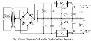
For op-amp circuits, the power supply must provide positive and negative voltages. Here is a simple circuit “Adjustable Bipolar Voltage Regulator” which gives a regulated ± 1.2V to ±2oV supply. ICs LM317K (IC1) and LM337K (IC2) are used here as positive and negative regulators respectively. Circuit Description of Adjustable Bipolar Voltage Regulator using LM337 The circuit diagram of the adjustable bipolar voltage regulator using LM337 is shown in figure 1, and is designed using two positive and negative adjustable voltage regulator IC, a step-down transformer, a bridge rectifier, and a…
Read MoreHex to Binary Converter Circuit
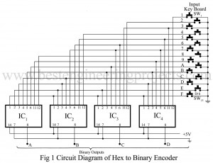
The circuit described here is a hex to binary converter circuit using four, 8-input NAND gate 7430 ICs. The input keyboard switches SW1 to SW15 are connected in such a manner that the pressing of any switch produces the binary ABCD outputs of the corresponding decoded numbers. When all inputs in a NAND gate are high, it produces a low output, But when any of its input goes low, its output becomes high. Normally, all switches are open, the binary output is 0000. Pressing a switch gives a ‘low input’…
Read MoreElectronic Siren Circuit using OP-Amp 741
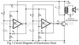
Here is an inexpensive electronic siren circuit built around the most popular and low-cost IC 741. The circuit is basically a square wave generator that is used here to produce the tone of a siren. Circuit Description of Electronic Siren Circuit using OP-Amp 741 The IC1 is used as a low-frequency multivibrator, the output of which modulates the high-frequency tone produced by the IC2 multivibrator. The final output is amplified and converted into a loud siren by transistor T1 and the speaker. Various interesting tones can be obtained by changing the…
Read More