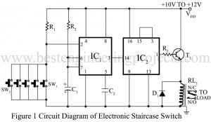
If you want to control an electrical appliance from two places then you use the 2-way switch. But to control it from more than two locations (like operating a hotel’s staircase light from individual floors from various locations), the circuit “Staircase Switch” comes to your help. Due to the small size of the staircase switch circuit, it can be installed within a junction box. Circuit Description of Staircase Switch Circuit Staircase Switch Circuit utilize IC1 (NE555) as a timer with timing of 0.7 seconds, for this it is configured in…
Read MoreCategory: Electronics Projects
3 Phase Induction Motor Starter
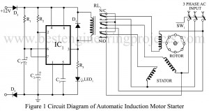
This circuit “3 Phase Induction Motor Starter” is one such starter. It is a very low-cost but highly reliable gadget, besides being fool-proof. Of all AC motors available, a polyphase induction motor is one that is mostly used in several kinds of industrial drives. this is because it is simple, extremely rugged, low cost, reliable, high efficient and requires little maintenance. Among the induction motors available, a squirrel cage machine is the best. However, such an induction motor can never be started by direct switching, as the motor can never…
Read MorePower Backup Circuit For Digital Clocks
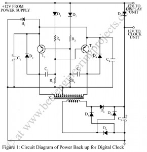
The usual method of using a 9V battery for backup in digital clocks, though common, is not very desirable for many reasons. The cost of the battery and the very short life are some of them. Circuit Description of Power Back-up Circuit for Digital Clock The circuit described here is a Power backup Circuit for a digital clock and it enables us to get the required 9V from just two penlight cells. Initially one has to invest in this circuit power backup for a digital clock, in the long run,…
Read MoreAnalogue Frequency Meter with Over-range Indicator
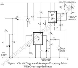
The versatile IC timer 555 has yet another application as an analog frequency meter. By making use of a 556 integrated circuit, which has two 555 timers in a single package, an over-range indicator can be economically added to the meter. Circuit Description of Analogue Frequency Meter with Over-range Indicator When this meter is switched to the 50Hz range, any input frequency from near DC to 50 Hz produces a correct panel meter reading, i.e. a frequency of 42 Hz produces a meter reading of 42 microamperes. However, the analog…
Read MoreIn- Circuit Ohmmeter (Ohmmeter for electronic Circuits)
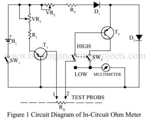
While servicing gadgets, changes often occur when you feel the necessity of checking a defective resistor, shorted diode, transistor, or capacitor in a circuit. Didn’t you desire that all could have been done without switching on the gadget and without de-soldering and extracting the components? Here is a simple and effective remedy called In-circuit Ohm-meter. All you need in two transistors are a few resistors. Circuit description of In-circuit ohm-meter When an emf of about 1.5 volts is applied across the emitter-base junction of a germanium transistor, an emf of…
Read MoreAuto-off for Cassette Players
Most common stereo cassette players have an auto-stop deck mechanism but do not have the auto power-off function. The circuit is meant for cassette players having an operational voltage of 12 V DC with the facility of LED type VU meter. When the sound signal stops, the power is automatically switched off after a delay of approximately 30 seconds. Circuit Description of Auto-off Cassette players With sound present, the LEDs of VU meter emits light. The LDR on receiving light from LEDs gives a high pulse to transistor T1which charge…
Read MoreRunning Light Circuit
In many situations, whenever a running light effect is required, a wooden wheel switch is needed. The wheel is driven by a motor which normally connects three switches, one by one producing a running light effects. Such a switching is very bulky and troublesome. Here is a simple electronic project “Running light circuit” with a very few components but which is equally effective. Circuit Description of Running Light Circuit In the circuit running light all transistors remain on except one which is off. This off sequence ‘travels’ through each transistor.…
Read MoreMulti-Pattern Running Light Circuit
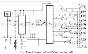
Running lights effect is not a new idea for electronics hobbyist. But this multi-pattern running light becomes unique as four patterns can be selected. In the first pattern, out of eight lights, alternate light go ‘on’ and ‘off’. In the second pattern, two adjacent lights go ‘on’ and the following two go ‘off’. This pattern is shifted from left to right. In the third pattern, four adjacent lights go ‘on’ and these are sifted to right. In the fourth pattern all the eights light go ‘on’ and ‘off’ one by…
Read MoreElectronics Number Scoring Game
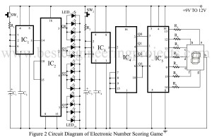
We have already posted few interesting electronics game project. Now, here is one very interesting game projects “Electronics Number Scoring Game” which can give you hour of fun. You can play electronics number scoring game alone or with some friends. Circuit Description of Electronics Number Scoring Game The circuit of electronics number scoring game uses two timer ICs i.e. NE 555 (IC1 and IC3) to generate clock pulse and a decade counter to generate mathematical sign. A BCD counter followed by a seven-segment LED display driver is used to generate…
Read MoreDouble tune Car Reverse Horn
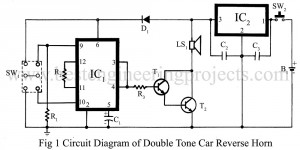
Several circuits of musical car horn have been published in BEP but “Double tune car reverse horn” differs from them. Projects like this helps you to get more used to various electronic devices. The circuit that produces the double tune car reverse horn generates two types of sounds: one is a pleasant ‘ding-dong’ bell sound and the other one is a sweet chirping sound of a bird. Here, the IC HT82D (IC1) is used as the sound generator whose operating voltage range is 2 to 5 volts. It has 10…
Read More