While servicing gadgets, changes often occur when you feel the necessity of checking a defective resistor, shorted diode, transistor, or capacitor in a circuit. Didn’t you desire that all could have been done without switching on the gadget and without de-soldering and extracting the components? Here is a simple and effective remedy called In-circuit Ohm-meter. All you need in two transistors are a few resistors.
Circuit description of In-circuit ohm-meter
When an emf of about 1.5 volts is applied across the emitter-base junction of a germanium transistor, an emf of about 0.25 volts develops across the collector-base junction, and this is the basic ‘drug’.
The basic problem in checking the value of the resistor in a circuit is that our multi-meter supplies about three volts across the test prods. This 3V is sufficient to forward bias the diode or transistor junctions in the circuit, providing a stray current path between the checkpoints. Thus the reading of the multimeter is that of effective resistance and not of the actual resistor value.
But if we apply around 0.25 volts to the test prods, the silicon junction is not conductive, since it needs a minimum of 0.6 V to conduct. Most of our modern circuit boards tend to have silicon devices as active elements. Therefore, it will ignore most of the common junctions such as those in bipolar transistors, signal diodes, rectifier diodes, Zener, varactor diodes, FET gates, etc, of course, except germanium devices which are becoming a rare entity.
In the circuit in circuit ohm-meter, transistor T2 has its emitter biased by 0.6V with the help of a potential divider. 1N4001 or any general-purpose silicon diode may be used for this purpose. The collector of T1 being at about 0.25V, the test prods of in-circuit ohm-meter now develop 0.35V potential difference across them, which is insufficient for the silicon junction to conduct. Pot VR1 (1K-ohm) and VR2 (2.2K-ohm) are meant for zero setting in the low resistance and high resistance mode respectively. The DPDT switch converts the circuit in circuit ohm-meter to multimode-high resistance/low resistance modes.
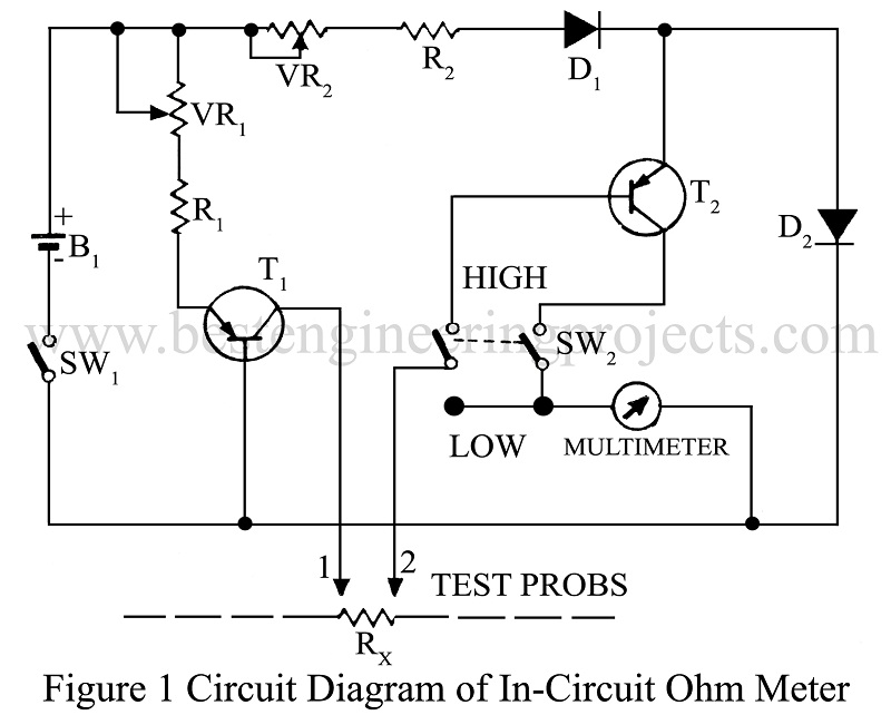
For zero setting of in-circuit ohm-meter put your multi-meter in the 0.25V range and connect it to the meter. Now short the test prods 1, 2 and adjust VR1 in low resistance mode to get an exact full-scale deflection on the meter; and your improve in-circuit ohm-meter is ready. Surprisingly, you will find that you need not worry about the scale at all! I use general SANWA p3 multi-tester (175 µA, 500-ohm movement) and its ohmmeter scale is marked 10K/100-ohm in the middle, and in this mode, it reads 1 K at this place, that is, a midway scale, 1/10th of the high resistance range and 10 times the low range. The in-circuit ohm-meter now runs from 10 ohms to 100 K maximum measurements, which is by far the most prevalent range of resistances in general circuits.
In the high resistance mode of in-circuit ohm-meter, however, the characteristics of transistor T2 play a key role. It is not possible to provide any guidelines about the calibration of the scale, since it depends upon the type of the transistor is working in the lowest part of its characteristics.
The germanium transistor has a small emitter-collector current flowing even with an open base (infinite resistance). To avoid the problem considerably, a small-signal transistor is advised for this stage (transistor T2), since a very low current of the order of 0.25 µA max. is the requirement.
So if you wish to build this double mode in-circuit ohm-meter, an exclusive meter movement is recommended, wherein you can make your own scale for the two modes. Or if you use your own multimeter, don’t mess up the already burdened scale; rather prepare a conversion table for the high resistance mode.
PARTS LIST OF IN CIRCUIT OHM-METER
|
Resistor (all ¼-watt, ± 5% Carbon) |
|
R1 = 470Ω R2 = 1 KΩ VR1 = 1 KΩ VR2 = 2.2 KΩ |
|
Semiconductors |
|
T1, T2 = AC128 D1, D2 = 1N4001 |
|
Miscellaneous |
|
SW1 = On-Off switch SW2 = DPDT-Switch B1 = 1.5V Battery Test prods Multi-meter |