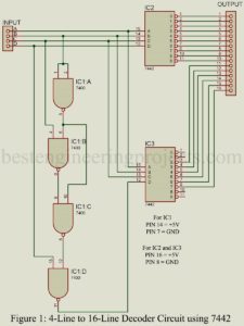
Decoders are essentially an arrangement of logic elements that are combined to change from are digital code to another. The term ‘decoder’ is most frequently used but depending on the point of view, the term ‘encoder’ is equally correct. Figure 1 shows the circuit diagram of a 4-bit, 4-line to 16-line decoder using two 7422 4-line to 10-line decoder IC . The input A, B, C and D can represent any logic function and the output 1 through 16 will then provide the addition or the logic or function of…
Read MoreCategory: Electronics Projects
Solder Fumes Extractor Circuit
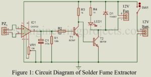
Solder Fumes Extractor Circuit: Soldering in electronics is analogous to fixing a component using glue. It is a general phenomenon in the field of electronics that involves fixing electronic components into a special board called PCB with the help of instruments like soldering iron and electrical solder commonly called ‘Solder wire’. While soldering we all face the problem of toxic fumes. These fumes are of lead solder wire and flux. Combinedly, these fumes are highly toxic if an excess amount is inhaled. To solve this problem, here we designed a…
Read MoreAudio Distribution Amplifier Circuit using LM324
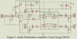
Audio Distribution Amplifier is a circuit which transfer signal from one audio source to many output with a facility of appropriate amplification. The project published here is of Audio Distribution Amplifier Circuit using LM324 is shown in figure 1, which is basically a low cost, low noise amplifier designed using one of the most popular operational amplifier LM324. The circuit of audio distribution amplifier is combination of low noise input transistor amplifier and an op-amp in order to insure good characteristics. Circuit Description of Audio Distribution Amplifier using LM324 The circuit…
Read More20 Watt Audio Amplifier using TDA2003
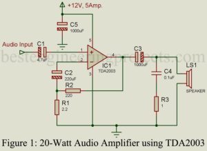
Here is a simple circuit of the “20-Watt Audio Amplifier using TDA2003″ IC to amplify the weak audio signal. Various types of amplifier circuits have already been posted in the amplifier circuit section. The IC TDA2003 contains a pre-amplifier, driver amplifier, and output amplifier internally. Basically, TDA2003 is an improved version of TDA2002 with various features like very low harmonic distortion and high output current capability. Circuit Description of 20-Watt Audio Amplifier using TDA2003 The circuit of the 20-Watt Audio Amplifier using TDA2003 shown in figure 1, build around the…
Read More10-Watt Audio Amplifier
The Driver Amplifier amplifies the weak electrical signal from the microphone and makes it suitable for power amplification. Thus, an amplifier that is used before a power amplifier is called a driver amplifier. As all amplifier driver amplifier is also a cascade amplifier. Thus, by cascading multiple amplifier stages a project 10-Watt Audio Amplifier is built. Circuit Description of 10-Watt Audio Amplifier The project shown in figure 1 is of 10-Watt Audio Amplifier, which is basically a combination of various amplifiers i.e. pre-amplifier, driver amplifier, and a push-pull amplifier. Here…
Read More12V DC Ballast Circuit
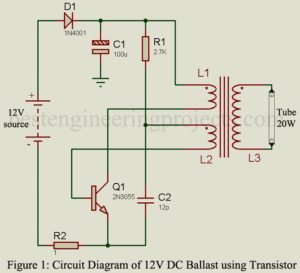
The project “12V DC Ballast” using power transistor 2N3055 is used to glow AC tube light using a DC source. The circuit of DC ballast is a DC-to-AC converter. DC ballast of various capacities (in watts) is already available in markets. The circuit posted here is of 20W capacity i.e. (it can drive a load up to 20 watts). Previously, we had posted Electronic Blast for Tube-light which drives load up to 40W, double the power of 12V DC Blast. Circuit Description of 12V DC Ballast The circuit of 12V DC…
Read MoreDigital AC/DC Voltage cum Continuity Tester
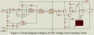
The project “Digital AC/DC Voltage cum Continuity tester” can be used to test 25 Volts to 500 volts AC/DC voltage continuity and open-circuit condition by displaying on the 7-segment display. There is the various advantage of “Digital AC/DC Voltage cum Continuity tester” over multimeter are Small Size, low cost, easy operation and requires no troublesome selector switch to select testing mode. To make a selector switch free circuit, we had used 82K impedance for DC and 220K impedance for AC. The testing procedure is very simple all you have to…
Read MorePhase Sequence Change Indicator
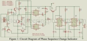
The project phase sequence change indicator using 555 IC is used to indicate whether there is a change in phase sequence occurring or not by a beeper or a LED. We all know that in three-phase motor phase sequence is important because the change in phase sequence may cause trouble in machines. Circuit Description of Phase Sequence Change Indicator The circuit of phase sequence change indicator is divided into two main sections i.e. controlling section and the beeper section. The circuit of the phase sequence change indicator is shown in…
Read MoreArduino FM Transmitter
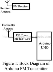
The project “Arduino FM Transmitter” is a radio station with transmits either voice or music nearby area, within the range of 50 meters range. The transmitted FM signal is received by any FM receiver. Previously, we had posted an Arduino-based FM Receiver with the facility of automating or manual tuning. The project uses very few components i.e Arduino uno board (MCU) and an FM transmitter V2.0 module. This project has various applications like it can be implemented in college hospitals etc. where announcements have to do. The block diagram of…
Read MoreAutomatic Night Lamp Circuit
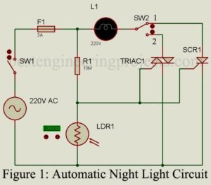
The project “Automatic Night Lamp Circuit” is very simple and built around four major components i.e. TRIAC, SCR, LDR, and Resistor. The lamp used in this project is a porch light that would turn on automatically in dark (nighttime) and turn off in light (daytime). Circuit Description of Automatic Night Lamp Circuit The circuit of Automatic Night Lamp Circuit is used shown in figure 1. The circuit is very simple and straightforward that anyone has very little knowledge about TRIAC and SCR. Silicon Controlled Rectifier | Automatic Night Lamp SCR…
Read More