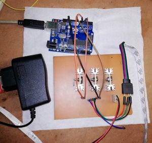
In the tutorial Arduino MOSFET LED driver circuit, you will learn to make your MOSFET Driver for any higher power appliance like LED Strip, high power DC motor, etc. We all know that we need a driver circuit to control high-power appliances like DC motors, electrical appliances, etc. So, here we are using MOSFET to control the operation of the LED strip. If you want to know more about MOSFET, its type, Symbol, application, and characteristic curve please do read the previous article on MOSFET | Types of MOSFET |…
Read MoreCategory: Led Projects
LED Projects: Various type of electronics project using LED like LED matrix, LED Cube, Sound level meter, LED Chaser circuit, running light and many more.
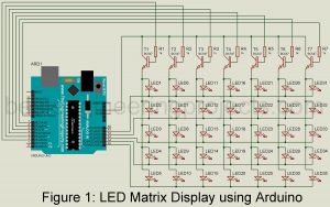
LED Matrix Display using Arduino
Today, I am going to teach you how to make an LED matrix display using Arduino. Here we had designed a 7×5 LED matrix display but can be extended as per desire. If you are using Arduino uno board the number of rows can be extended up to 14 and the number of columns can be extended up to 6. This is because there are only 14 digital pins (D0 to D13) and 6 analog pins (A0 to A5). Thus, you can make a 14×6 Led matrix display in the…
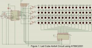
Read MoreLED Cube 4x4x4 Circuit using AT89C2051
The world is all about visualization. Mesmerizing illumination has been introduced which provides a different level of satisfaction for human eyes. Using multi-pattern LEDs lights in a cubical representation is our contribution to this global trend. The project; LED Cube 4x4x4 Circuit using AT89c2051 microcontroller to create several light patterns. The cube designed for specific use in science laboratories is much easier to assemble. Previously, we had posted an LED Matrix Display using Arduino. Circuit Description of LED Cube 4x4x4 Circuit using AT89C2051 You can see the entire circuit of…
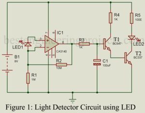
Read MoreDIY Light Detector Circuit using LED
Today we come with a unique idea i.e. Photodiode using LED. This project utilized an LED to detect and respond to the presence and absence of light. Before starting the description and working of circuit DIY Light Detector Circuit using LED, we would like to describe a few electronics components. LED: Light-emitting diode is a photoelectric device that converts electrical energy into light energy. It is a heavily doped P-N junction diode that under forwarding bias emits spontaneous radiation. Photodiode: Photodiode is an optoelectronic device in which current carriers are…
Read MoreSound Level Meter Circuit
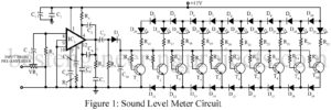
The project sound level meter circuit shown here comprises a display circuit for 10-segment resolution i.e. used to indicate sound level up to 10 levels. Recording of sound in the studio involves critical adjustment of recording levels and level of bias current. If the level of sound is very much it may cause some distortion while a low level of sound reduces the SNR (Signal to Noise Ratio) as a result the sound may be too noisy. Care should be taken while recording sound to regulate the signal so that…
Read MoreLED Chaser Circuit Using NE555
Various types of LED-based projects are already posted on bestengineeringprojects.com. Now, here is a simple project called LED chaser Circuit using NE555 in which 10 different LED is arranged in a column. The LED arranged in column glow from top to bottom, one at a time. Description of LED Chaser Circuit Using NE555 The circuit of the LED chaser is designed around a timer IC NE555 (IC1) and decade counter IC CD4017 (IC2). Here, IC1 is used in astable multivibrator mode which generates a clock pulse in a fixed interval…
Read MoreLED Running Light Circuit
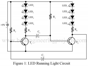
Various types of running or disco lights are already available on bestengineeringprojects.com. Now here very simple LED Running light circuit using two transistors. Circuit Description of LED Running Light Circuit: The entire circuit of LED running light is designed using two general purpose NPN transistors. The design and working of this circuit are very simple and straightforward. Both of these transistors are configured in astable multivibrator mode. Initially when no power supply is connected, both the transistor drives to cut off region and none of this LED glow. But when…
Read MoreDisco Light Circuit
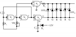
Blinking and shimmering of lights in disco keep everyone amazed, the entire design cost of which might seem high. A circuit is presented hereby is of disco light making use of low-cost CMOS chip CD4011B, which is a two-input quad NAND gate. Along with two particular gates; G1 and G2 as shown in the figure below, it works as an RC oscillator forming clock oscillator gates. Circuit Description of Disco Light Circuit Here the two input terminals of the CMOS chip are coupled together to form an inverter. And, again…
Read More