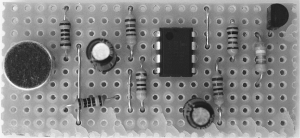
The engineer like to communicate with their mates but radio wave is too easy to intercept using light with morse code is tricky. Here Laser Voice Transmitter Circuit uses a laser beam to transmit the voice. Circuit Description of Laser Voice Transmitter Circuit:- Most all communication systems comprised of two parts, the project laser voice transmitter also comprised of two parts i.e. the transmitter circuit and the receiver circuit. The transmitter circuit:- The transmitter circuit is built using a microphone, audio amplifier, laser diode, and a few passive components. A…
Read MoreCategory: Electronics and Communication Projects
Various types of electronics and communication projects (ECE) projects are listed in this categorey, 50+ ECE projects with PCB design
DTMF Based Remote Control System
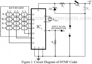
Different gadgets have been introduced to meet our requirements ranging from basic needs to classy needs of humans. With this development in recent years, day by day people has grown more sophisticated. Putting human comfort as a main concern, hereby we have presented a circuit to remotely control several electrical or electronic gadgets connected to it. The unique feature of the circuit DTMF-based remote control system in comparison to other remote control systems like IR remote control is that this circuit employs FM transmission and reception, for this reason, it…
Read MorePhone Broadcaster Circuit
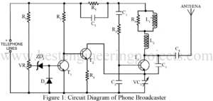
An interesting circuit design that is also used as a wireless telephone amplifier, is demonstrated below which has been proven very useful in prying on a telephone conversation and therefore is termed a phone broadcaster circuit. The more amazing or we can say a comforting fact about the phone broadcaster circuit design is that it draws the power essential to operate the circuit directly from the active telephone lines. Therefore, it avoids additional expenses in external battery and prevents the circuit from the extra bulkiness of other power supplies. Circuit…
Read MoreMedium Speed Modem Using SC11004
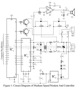
Modems have been often been stand-alone, add-on devices for most data communications equipment. The recent integration of the complex functions a modem performs into a single chip has allowed manufacturers to economically build the modem right into the microcomputer or data terminal equipment. A circuit diagram of such a modem is shown in figure 1. Circuit Description of Medium Speed Modem Using SC11004 All of the signal processing functions needed for a full-duplex, 300/1200-b/s modem, including the FSK and PSK modulators and de-modulators, are integrated on a single chip. It includes…
Read MorePulse Width Modulation using 565 IC
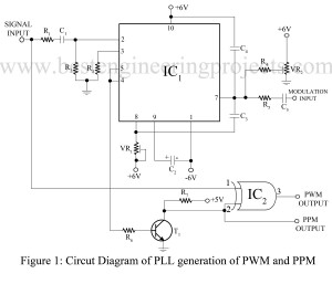
Pulse Width Modulation (PWM) is a technique to control the average power delivered to the analog devices. With an acquisition of 555 IC amongst most people working with electronic devices, the use of 565 IC is like using two 555 ICs inside a single device. Unlike 555 IC, 565 IC has 14 pins which act as a dual timer. 565 IC is also available with 10 pins. Nevertheless, they both require the same amount of power supply. PWM using 565 IC is a form of Pulse Time Modulation (PTM), also…
Read MorePWM Generator and Class D Power Amplifier
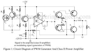
PWM (pulse-width modulation) forms the basis for a very efficient form of power amplification. The circuit in figure 1 is a so-called class D power amplifier since the actual power amplification is provided to the PWM signal, and since it is of constant amplitude. The transistors used can function between cutoff and saturation. This allows for maximum efficiency (over 90%) and is the reason for the increasing popularity of class D amplifiers as a means of amplifying any analog signal. Circuit Description of PWM Generation Class D Power Amplifier The…
Read MoreFrequency Shift Keying (FSK) Generator Using PLL 565
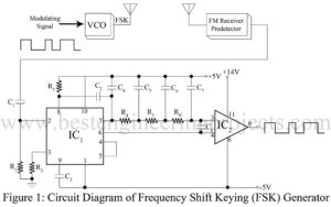
a boat in tempest-tossed seas? That’s approximately what Frequency Shift Keying (FSK) accomplishes—it’s a method of data transmission through frequency alternating on and off, like Morse code in the ether but infinitely, infinitely faster. How FSK Generation Works One way to generate FSK is by tweaking the capacitor in an oscillator’s tank circuit. When the transmitter is keyed, the capacitor kicks in, changing the frequency. In narrowband FSK, instead of fiddling with capacitors, you can shunt capacitance across a crystal and let frequency multipliers do the heavy lifting. Another way?…
Read MoreLow Frequency Sine Wave Synthesizer
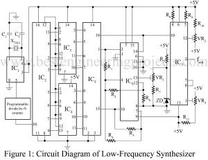
The generation of low frequency is generally accomplished with an RC oscillator. The techniques recently developed for frequency synthesis can now be used conveniently with very precise low frequencies required. A low-frequency sine-wave synthesizer well demonstrates accuracy and stability characteristics that can be measured in part per million (even at 0.01 Hz) if it is crystal controlled. Circuit Description of Low Frequency Sine Wave Synthesizer The synthesizer in figure 1 is based on an 8-bit digital-to-analog converter IC AD7523 (IC5) which presents a precise triangle wave to the timing of a…
Read MoreFiber optic telemetry system Using NE555
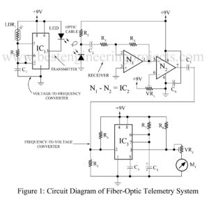
Complete fiber optic systems are finding widespread use in all types of applications figure 1 provide a very simple fiber optic telemetry system using NE555 that can be used in a variety of telemetry application essentially. The transmitter is an astable oscillator using the popular NE555 (IC1). Circuit Diagram of Fiber optic telemetry system Using NE555 The variable resistance LDR1 contract the rate of the pulse applied to the LED. LDR1 can be any variable resistance transducer such as a strain gauge for pressure sensing, a thermistor for temperature sensing, or…
Read MoreTelephone Converter Circuit
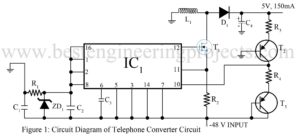
A telephone converter circuit that can be used to power the circuit added to the basic phone is shown in figure 1. This may be more economical/convening than adding a separate power supply from the AC power line or using battery power. It takes the -48V provided by the telephone and efficiently converts it to a well-regulated 5V. Circuit Description of Telephone Converter Circuit A telephone converter circuit does not require the bulk and expensive transformer which is usually used in these designs. It takes the -48V (it can function…
Read More