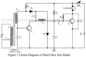
Multiband CW Transmitter

circuit diagram of multiband cw transmitter

A frequency oscillator is used to generate frequency oscillation, and a radio frequency oscillator is used to generate high-frequency which is known as a carrier wave. The circuit multiband CW transmitter is a continuous wave (CW) transmitter for transmitting morse code signal in a shortwave band. The circuit posted here is a variable frequency oscillator (VFO) whose frequency can be varied from 5.2 MHz to 15 MHz. The transmitted signal from this circuit can be received in a short wave band by any radio receiver. Circuit Description of Multiband CW…

Read More

Pocket Radio Using LA4510

pocket radio circuit using LA4510

Here is a circuit for a pocket radio using one IC LA4510 and three transistors. This circuit differs from ordinary circuits at the audio stage only. Here a small 9-pin IC LA4510 is used. It replaces three transistors, a driver transformer, and many other passive components. The amplifier circuit needs only one resistor! At zero signal level, this circuit draws 8-10 mA current only. With a 3-volt supply, this circuit can give 200 mW output power. For making this radio you may buy an ordinary pocket radio PCB and assemble…

Read More

Frequency Multiplier Circuit

programmable frequency multiplier circuit

Here is a  Frequency Multiplier circuit using PLL565.  Phase lock loop (PLL) has many diverse applications, among its applications PLL exhibits tremendous flexibility in frequency multiplication.  The IC 565 (IC1) can be used over the frequency range of 0.001 Hz to 500 kHz, and an operating voltage range of 6V to 12V. The frequency multiplier circuit  has a highly stable center frequency, selected by an external resistor (R1) and Capacitor (C1), which is given by The capture range of the feedback control system of the frequency multiplier circuit is decided…

Read More