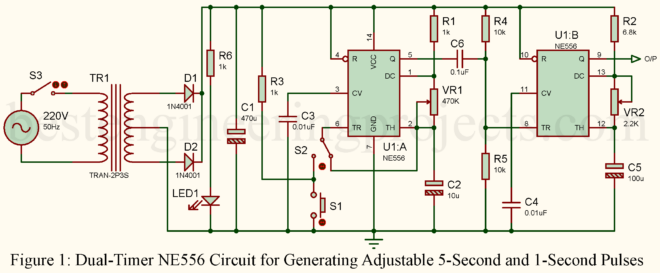
There’s something undeniably magical about creating a circuit that pulses like a heartbeat, ticking away with precision. That’s what this Dual-Timer NE556 Circuit is all about—it’s a simple yet powerful design that spits out two different pulse durations, one after the other, like clockwork. If you love tinkering or need a timing solution, this little gadget is your new best friend. What Does It Do? Imagine standing in a room, flipping a light switch on and off every five seconds. Now, imagine that after every “off,” someone else presses another…
Read MoreCategory: 555 Timer Projects
Fastest Finger First Circuit with 7-Segment Display and Alarm
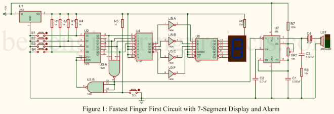
Imagine you’re on stage, heart pounding, eyes locked on the big screen in front of you. The host asks the final question—this is it. Your reflexes are sharp, your hand hovers over the buzzer, and then BAM! You slam that button down faster than a cheetah chasing its dinner. But how does the system know you were the first? That’s where the Fastest Finger First Circuit steps in. This little piece of engineering magic can make or break a game show, quiz night, or classroom competition. Today, we’re diving into…
Read MoreEfficient Low Dropout MOSFET Regulator with 555 Timer Charge Pump
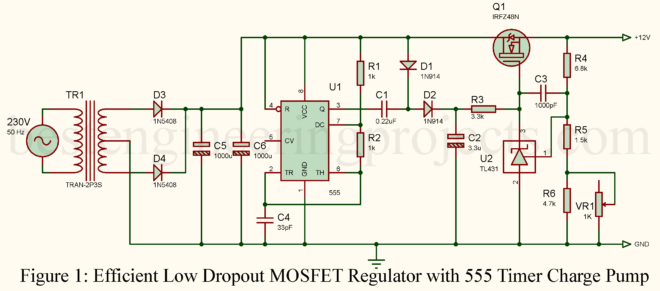
Efficient power regulation with a minimum drop in voltage has become quite necessary in modern electronics, especially when one works with low-voltage DC supplies. It is in meeting such requirements that a Low Dropout MOSFET Regulator becomes handy-assuring stable output with reduced dissipation of power. The following article elaborates on the design for an Efficient Low Dropout MOSFET Regulator, employing a 555 Timer Charge Pump to develop a higher gate voltage for the MOSFET, thereby realizing ultra-low dropout performance. Why Use a Low Dropout MOSFET Regulator? In conventional linear regulators,…
Read MoreHow to Build an Infrared Jammer Circuit
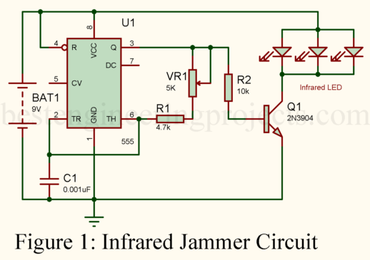
The infrared jammer circuit can be utilized for either practical means or to create a fun experiment. The general idea is that this little contraption is supposed to be powered by a high-powered infrared light that works against any gadget dependent on infrared signals, including TV remotes, auto-focus cameras, and even devices of the spy class. In this guide, you’ll learn how to build your own infrared jammer circuit to block infrared signals in a room. This tutorial is ideal for hobbyists and those interested in counter-surveillance. How Does an…
Read MoreBuilding a Programmable Touch Power Supply Circuit
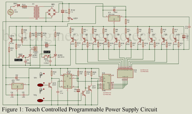
Today, many gadgets use touch control – a simple touch makes things happen and adds a modern touch. People who enjoy electronics are creating their power supplies with LM317 variable IC regulators and special switches for power adjustments. There’s a cool project here called the “Programmable Touch Power Supply Circuit” It’s not just a regular power supply – it has touch magic. You can change settings by touching it, mixing tech with simplicity. Imagine devices without buttons – this project uses touch sensors. No searching for buttons – just touch…
Read MoreFrequency Shift Keying Demodulator Circuit
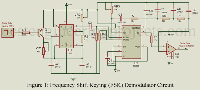
Frequency Shift Keying (FSK) plays a significant role in the field of computer peripheral and wireless communication, facilitating the transmission of binary data or code. This technique involves the manipulation of a carrier frequency, which undergoes precise shifts between two pre-established frequencies. The utilization of FSK allows for efficient and reliable data transfer. Description of Frequency Shift Keying Demodulator Circuit An area where FSK finds particular utility is in demodulating signals, and the 565 phase-locked loop (PLL) serves as an excellent tool for FSK demodulation. In this context, a binary…
Read MoreTransistor and Diode Tester using 555 IC
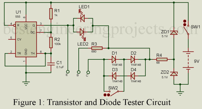
Transistors and diodes are fundamental components in electronics and play a significant role in many circuit designs. When it comes to incorporating these active components into a circuit, it’s crucial to ensure that they are working correctly. Therefore, it’s essential to have a reliable method to test transistors and diodes. Circuit Description of Transistor and Diode Tester using 555 IC In this article, we will discuss a simple yet effective transistor and diode testing circuit that can help you identify whether these components are functioning correctly or not. The circuit…
Read MoreWater Flow Detection with Alert System using 555 IC
Sometimes we have to check the water supply pipeline from the municipal whether water is coming or not. Though the supply interval is fixed, the supply time may vary accordingly. It is quite possible to forget to switch on the motor, which results in no water in the reservoir. The article named, “Water Flow Detection with Alert System using 555 IC” is written to tackle such situations. In this article, you will learn to construct a simple water flow detector circuit. The circuit basically triggers the alarm when the water…
Read MoreCalling Bell Circuit Diagram
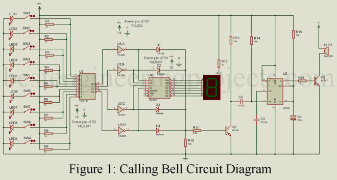
In this article, we are satisfying the curiosity of electronics hobbyists, you and I alike by making a calling bell circuit diagram. The project can be set up in different rooms of an office or hospital and the attendant or office boy waiting place or nursing station. When a call is made from any of the rooms the attendant can be notified through the bell and he/she can verify the room from which the call is made by looking at the display showing the room number. Thus this project allows…
Read MoreAutomatic Solder Smoke Extractor
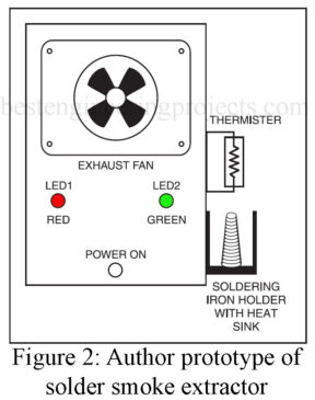
Automatic Solder Smoke Extractor: Soldering is the process of joining electric/electronic components together. It is a very basic and most used process in the field of electronics because it is used to establish a secure connection between PCB and the components. Multiple types of solder wire are available at the market varying in dimensions and quality. Although there are multiple types of solder wires almost all of them are made from Lead and tin. Only the heated iron melts the wire so it is a must to let the iron…
Read More