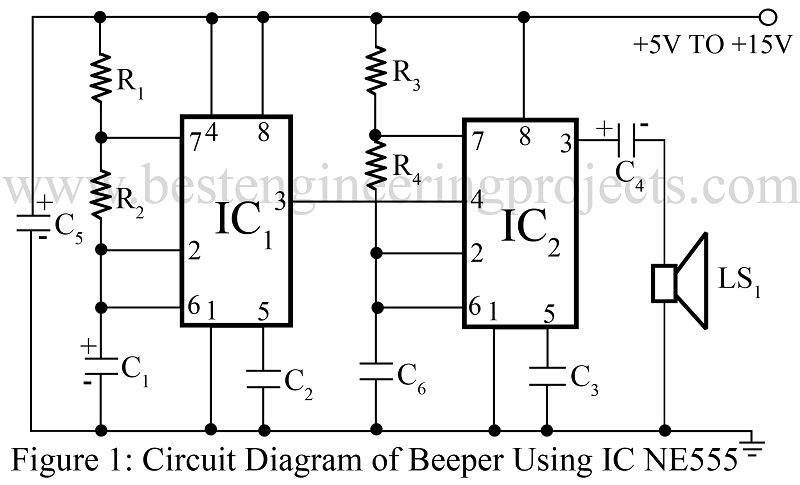
Here is a beeper circuit employing two timer ICs NE555 (IC1 and IC2). The beeper circuit using timer IC NE555 can be used in various circuits that require an alarm or a ‘beeping’ signal.
Description of Beeper Circuit Using Timer IC NE555
Timer IC1 is used here in astable mode in such a way that square-wave output at about 1 Hz is obtained. IC2 is also configure in astable mode, but it gives an output with about 1 kHz frequency.
The output if IC1 (pin 3) is connected to ‘Reset’ terminal (pin 4) of IC2. So, this continuous 1 kHz tone of IC2 is interrupted by the 1 Hz signal from IC1, producing a ‘beeping’ sound. Capacitor C4 is used to restrict DC signals.
The beeper circuit operates satisfactorily when it is to be activated by a relay or a mechanical switch, but when it is to be operated by logic ICs, such as CMOS or TTL ICs, a bit of modification is required. Instead of connecting pin 4 of IC1 to Vcc, it should be connected to the output of the logic element through which it is to be activated. A logic ‘1’ at pin 4 will activate the beeper and logic ‘0’ will turn it off. Rest of the circuit would remain the same.
Check out other interesting alarm circuit posted in bestengineeringprojects.com
- Electronic Siren Circuit
- 12 Tones Door Bell
- Steam Whistle Circuit
- Simple Warning Alarm Circuit
- Rain Sound Generator Circuit
PARTS LIST OF BEEPER CIRCUIT USING TIMER IC NE555
|
Resistor (all ¼-watt, ± 5% Carbon) |
|
R1, R3 = 1 KΩ R2 = 680 KΩ R4 = 10 KΩ |
| Capacitors |
| C1 = 1 µF, 25V (Electrolytic Capacitor)
C2, C3 = 0.01 µF (Ceramic Disc) C4 = 33 µF, 25V (Electrolytic Capacitor) C5 = 100 µF, 25V (Electrolytic Capacitor) C6 = 0.047 µF (Ceramic Disc) |
| Semiconductors |
| IC1, IC1 = NE555 (Timer IC) |
| Miscellaneous |
| LS1 = 8 Ω, loudspeaker |

Can you explain why we don’t use an astable multivibrator itself as signal to the loudspeaker. I want to know the need for 2 555 timers.
Please read the article through-out once before asking question.
I mention in article why I used two 555. please refer to the line “this continuous 1 kHz tone of IC2 is interrupted by the 1 Hz signal from IC1, producing a ‘beeping’ sound.”
how can i attach it in my existing circuit as a controller of beeping sound?