Today, in this article we are going to teach you how to make an automatic fence lighting circuit with an alarm using op-amp 741 and timer IC 555. Fence lighting is used for security purposes and can be used at various places like door alarms, pathway alarms, etc. where monitoring is required.
Various types of fence lighting circuits are already available over the internet but the problem with that circuits is they required high precision alignment. To overcome this problem, we designed a very sensitive automatic fence lighting circuit. We had not used any inbuilt light source, you can place this circuit within the line-of-sight to any light source like sunlight, electric light, etc.
Description of Automatic Fence Lighting Circuit with Alarm
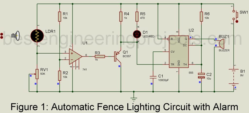
The circuit of automatic fence lighting circuit with alarm is shown in figure 1. The construction of this project is very simple and is built around readily available electronics components like op-amp 741, timer IC 555, PNP transistor BC557, LED, piezo buzzer, and a few other passive components like resistor and capacitors.
IC741 is configured in voltage comparator mode where resistor R1 and R2 a voltage divider that provides reference voltage and LDR with variable resistor RV1 is also a voltage divider and provide signal voltage. Timer IC 555 is configured in monostable multivibrator mode where resistor r6 and capacitor C2 are responsible for time delay because these two components are called the time constant.
A voltage comparator compares a signal voltage on one input of an op-amp with a known voltage called reference voltage on the other input. This circuit is also called a non-inverting comparator because Vin (input voltage signal) is given to the non-inverting pin (pin 3).
The reference voltage of about ½ of 4.5V is available at inverting input (pin 2) and the signal voltage to be compared is available at the non-inverting input (pin 3) from the potential divider network build using LDR and VR1. The output may be high (+) and low (-) saturation voltage, depending on which input is larger.
When Vin at pin 3 is greater than Vref at pin 2 then the output of IC1 will be high, which drives transistor T1 in the off state. As a result, LED becomes off and IC2 is also stopped from oscillating. Similarly, when light is interrupted on LDR, the voltage (Vin) at pin 3 is less than Vref voltage (voltage at pin 2) as a result the output of IC1 (741) becomes low. This low output trigger timer IC 555 (IC2) activates the piezo buzzer for a definite time interval which is determined by resistors R6 and C2.
Various other basic electronics projects utilizing LDR:
- Light Sensor Switch Circuit using LDR and 741 IC
- Automatic Light Operated Switch using LDR and IC741
- IC 555 Based Automatic Evening Lamp
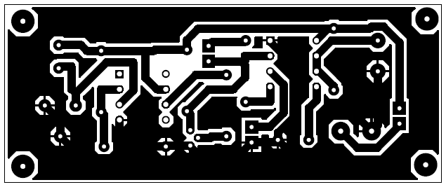
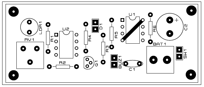
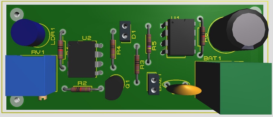
PCB Diagram:
PCB is designed using Proteus 8.1, download the PCB from the link given below.
Figure 2: Solder side PCB of Automatic Fence Lighting with Alarm
Figure 3: Component side PCB of Automatic Fence Lighting with Alarm
Figure 4: 3D view of Automatic Fence Lighting with Alarm
PARTS LIST OF AUTOMATIC FENCE LIGHTING CIRCUIT WITH ALARM
| Resistors (all ¼-watt, ± 5% Carbon) |
| R1, R2, R6 = 10 kΩ
R3, R4 = 1 kΩ R5 = 470 Ω RV1 = 50 kΩ (POT.) |
| Capacitors |
| C1 = 0.01 µF (Ceramic Disc)
C2 = 10 µF, 16V (Electrolytic Capacitor0 |
| Semiconductors |
| U1 = LM741 (Op-amp IC)
U2 = NE555 (Timer IC) Q1 = BC557(General Purpose PNP transistor) |
| Miscellaneous |
| B1 = 9V Battery
SW1 = Push-to-on Switch PZ1 = Piezo Buzzer D1 = 5mm RED Color LED LDR1 = Light Dependent Resistor |


