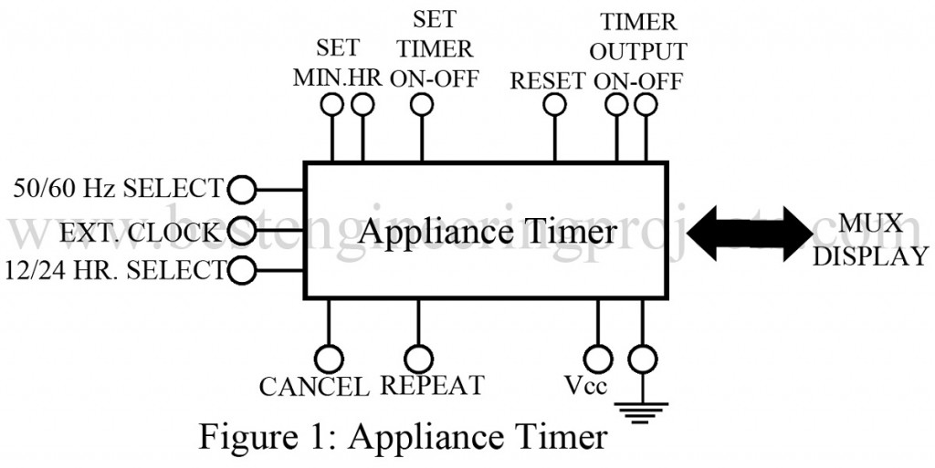
Generally, appliance timers offer a wide range of applications with a greater range of flexibility. But here we have presented a typical type of IC as shown in the figure, which can be used with 50/60 Hz power lines and can operate on both 12- or 24-hour basis. A 50 Hz power line requires an external clock input for operation.
This clock turns the timer on/off and along with this also sets the minutes and hours limits of the timer. Additional features like ‘reset’ and ‘repeat’ control are added, which set the timer back to the original time and allow the timer to repeat the operation as long as the respective control options are activated. Further, the ‘cancel’ control, terminate the alarm. The control output has separate arrangements of “on” and “off” lines that can go either directly to the appliance or to a relay to control the AC power to the appliance. Information to be displayed is multiplexed by segment and digit in the conventional manner.

Here are some basic parameters to further clarify the system
- Control logic levels- As we know logic levels ; logic 0 and logic 1 are two basic logic levels needed for any input and output controls. In this system, for a supply voltage of -12 V, typical value for logic 0 is +0.3 V and for logic 1 is -6 V.
- Display level outputs- The voltage levels required to turn the display segments on or off, are display level outputs. Depending on the type of display used, typical values vary from 0 to +5 V for LEDs and – 2 to 0 V for fluorescent displays.
- Maximum power dissipation- It is the maximum power loss to the surrounding. General value is 100 mW depending on the logic family.
Check out other clock and timer project posted in bestengineeringprojects.com
- Digital Clock with Seconds and Alarm Time Display
-
- Countdown Timer Using Arduino
- Industrial Timer Circuit
- Sound Activated 0-30 Minutes Timer Circuit
Applications of Appliance Timer
-Applicable in appliances as microwave ovens, TV tape recorders, electric cookers, stoves, etc.
Comments-
All inputs and output terminals may not be used in specified applications. In such cases, unused terminals must be connected to either to logic 0 or to logic 1 levels according to the manufacturers; prescription.