After completing this section, you should be able to troubleshoot the waveguide system. Waveguide problems are very similar to ordinary transmission line problems. The test equipment may look different, but it is doing the same things.
A word of caution: Waveguide is commonly used to carry large amounts of microwave power. Microwaves are capable of burning skin and damaging eyesight. Never work on waveguide runs or antennas connected to a transmitter or radar until you are sure the system is off and cannot be turned on by another person.
After completing Troubleshoot Waveguide System you should be able to:
- Identify problems caused by joints and flanges
- Detect arcing problems
- Troubleshoot rotary joint failures
- Detect malfunctions by determining VSWR in the guide
Some Common Problems:
- The joints or flanges between two waveguide sections are the most likely source of a problem. Sometimes, waveguides are pressurized to increase the power rating of the guide and keep water out. Improperly fitted joints can let water in and gas out. Water will raise the VSWR, which can damage most microwave tubes.
There are two types of flanges: choke and cover. Choke flanges have a groove cut into the face of the flange to keep microwave energy from escaping. There will be a second groove for a gasket. Cover flanges are simply very smooth. Both must be clean and flat. The screws must be the correct size since they help align the two pieces and keep them tightly sealed together. - Arcs. Arcs can occur at improperly fitted joints and actually burn holes in the guide. Arcs will occur in the waveguide under high power if some component such as the antenna has failed. You might see evidence of an arc on the broad wall right in the center of the guide.
- Worn out components. Radar antennas generally have one or more rotary joints. Rotary joints have bearings and sometimes moving contacts. Rotary joints sometimes fail only after the transmitter has had time to heat them sufficiently. By the time the technician has opened the guide and installed test equipment the joint will cool and test well. It is best to have a directional coupler in line while running the transmitter and watch for an increase in reflected power.
Rotary joints can also be tested on the bench by connecting the joint to a dummy load and measuring VSWR while turning the joint. Still, there will be no substitute for the operational test.
Flexible waveguide is subject to cracking and corrosion. Normally, the loss of a two-foot-long piece of the ridged waveguide is so low that the loss of the guide is extremely difficult to measure. A bad piece of the flexible guide can usually be detected by connecting a dummy load to it and measuring VSWR while flexing the guide.
Test Equipment for Troubleshoot Waveguide System:
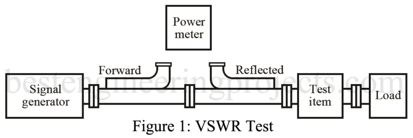
Figure 1 shows how to connect the test equipment for a VSWR test. First, connect the power meter to the forward (incident) power coupler and note the reading. Then connect the power meter to the reflected coupler and note the reading.
Reflected power should be very low, and the VSWR should be nearly one. VSWR is given by:
…..(Eq.1)
Where Pi = incident power
Pr = reflected power
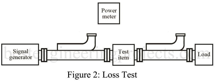
The same test equipment is used to measure loss by reversing the reflected couple and putting the test item between the couplers, as shown in figure 2. No two couples are exactly alike, so you must first connect them together without the test item and determine the difference. You should be able to make the loss measurement within 0.2 dB in this manner.

