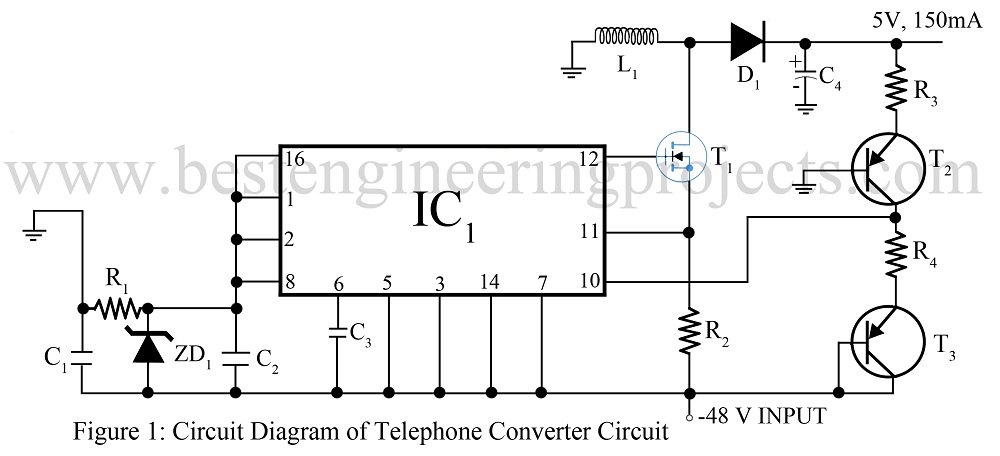
A telephone converter circuit that can be used to power the circuit added to the basic phone is shown in figure 1. This may be more economical/convening than adding a separate power supply from the AC power line or using battery power. It takes the -48V provided by the telephone and efficiently converts it to a well-regulated 5V.
Circuit Description of Telephone Converter Circuit
A telephone converter circuit does not require the bulk and expensive transformer which is usually used in these designs. It takes the -48V (it can function well with the input of -35V to 75V) and provides up to 150mA at 5V. The switching regulator (IC1 operates) in the boost configuration powered by a zener regulated 6.2V concerning the -48V. It, therefore, acts like it was converting 48V to 53V. A feedback signal is shifted in level from 5V to the IC’s feedback input (pin 10) by the current source transistor T1. Transistor T3 is included to compensate for the Vbe temperature drift in transistor T2. Transistor T3 can be omitted if about -2mA/0C voltage variation is acceptable.
The switching FET (T1) exhibits a typical RDS(on) of 1Ω when operating with the 6-V gate driver provided by the circuit. The efficiency of this circuit is about 75% and the 1Ω sense resistor (R2) limits the peak current to about 200mA.
Check out other phone/telephone related circuits posted on bestengineeringprojects.com
- Cell Phone Jammer Circuit
- Telephone Amplifier Circuit
- Add on Device For Telephone
- Telephone Spy
- Phone Broadcaster Circuit
PARTS LIST OF TELEPHONE CONVERTER CIRCUIT
| Resistor (all ¼-watt, ± 5% Carbon) |
| R1 = 47 KΩ
R2 = 1 Ω R3, R4 = 22 KΩ |
| Capacitors |
| C1 = 4.7 µF, 100V (Electrolytic Capacitor)
C2 = 0.33 µF (Ceramic Disc) C3 = 0.1 µF (Ceramic Disc) C4 = 330 µF, 10V (Electrolytic Capacitor) |
| Semiconductors |
| IC1 = MAX721 (Computer voltage regulator IC)
T1 = 2N7004 (N Channel MOSFET) T2, T3 = 2N5401 (High Current PNP Bipolar Transistor) ZD1 = 1N753A(6.2V Zener Diode) D1 = 1N5804 (Rectifier Diode) |
| Miscellaneous |
| L1 = CD54-151M(sumida) |
