The telephone spy circuit published here is used to hear telephone conversations remotely or to amplify the telephone conversations and also transmits the speech signals in the MW range so that one can listen to a telephonic conversation on a radio set.
The device picks up telephone conversations remotely if the telephone set is in the range of a few meters to some tens of meters, the device then amplifies the received signal and plays it through the speaker, and also transmits the signal as a Medium Wave signal.
The circuit can be used as a telephone spy or a telephone amplifier.
Check out other phone/telephone-related circuits posted in bestengineeringprojects.com
- Cell Phone Jammer Circuit
- Telephone Amplifier Circuit
- Add on Device For Telephone
- Phone Broadcaster Circuit
- Phone Broadcaster Circuit
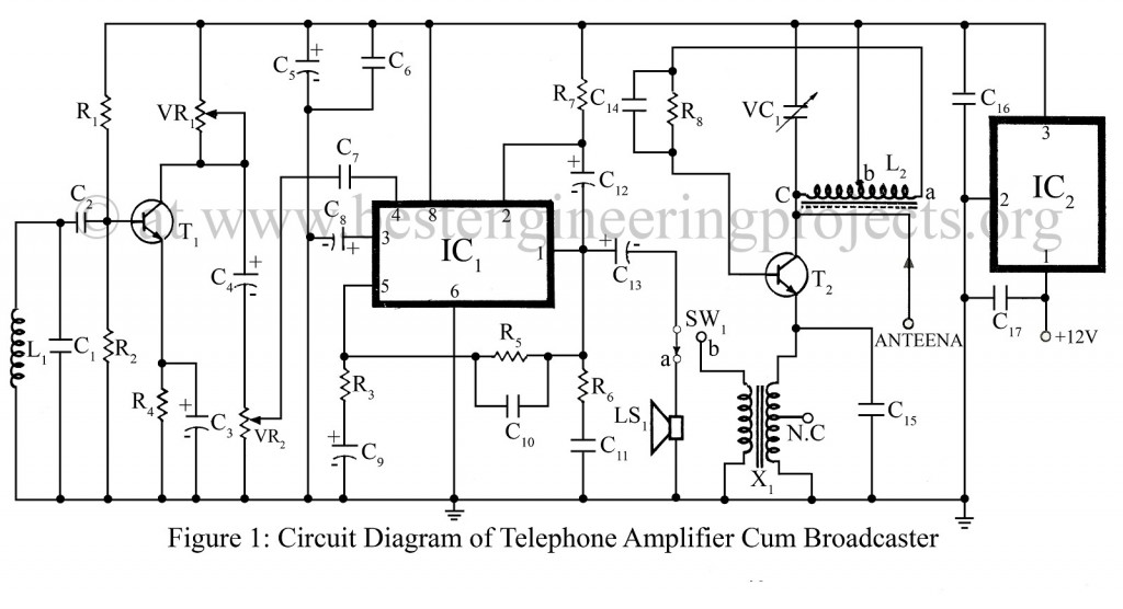
Telephone Spy Circuit Diagram:
PARTS LIST OF TELEPHONE SPY CIRCUIT
|
Resistors (all ¼-watt, ± 5% Carbon) |
|
R1 = 120 Ω R2 = 33 KΩ R3 = 470 Ω R4 = 1.8 KΩ R5 = 100 KΩ R6 = 1 Ω R7 = 47 Ω R8 = 47 KΩ |
|
Capacitors |
|
C1 = 0.02 µF (Ceramic Disc) C2 = 0.04 µF (Ceramic Disc) C3, C9 = 10 µF, 12V (Electrolytic Capacitor) C4 = 4.7 µF, 12V (Electrolytic Capacitor) C5, C13 = 470 µF, 16V (Electrolytic Capacitor) C6, C7, C11, C16 = 0.1 µF (Ceramic Disc) C8 = 100 µF, 12V (Electrolytic Capacitor) C10 = 330 pF (Ceramic Disc) C12 = 220 µF, 12V (Electrolytic Capacitor) C14, C15 = 0.01 µF (Ceramic Disc) VC1 = ½-2J GNAG |
|
Semiconductors |
|
IC1 = BEL-1895 (Power Amplifier IC) IC2 = LM7809 (9V Series Positive voltage regulator IC) T1 = BC547 (General Purpose NPN Silicon Transistor) T2 = BD139 (General Purpose NPN Silicon Transistor) |
|
Miscellaneous |
|
L1 = 3000 turns coil of 42 SWG enameled copper wire over 3.8 cm dia PVC pipe. L2 = a – b 15 turns 36 SWG b-c 75 turns 36 SWG enameled copper wire. X1 = Audio output transformer (Red Cover) SW1 = 2-way switch LS1 = 8Ω Loud-speaker |
Telephone Spy Circuit Description:
The heart of this circuit is a pick-up coil which is made of 3000 turns of 42 SWG enameled copper wire wound over 3.8 cm dia PVC pipe used as the former. After winding, remove the former carefully and wind self-adhesive (insulation tape) over the coil.
This coil is placed over the telephone set. A well-shielded wire should be used to connect the coil to the circuit. The length of this wire should be as short as possible. Users can determine the best position of the coil over the telephone set by trial and error to obtain the optimum results.
The audio signals picked up by coil L1 in the circuit are first amplified by transistor T1 which is wired as a simple common-emitter amplifier. Its output is given to the power amplifier wired around IC 1895.