Here in this article, we will learn how to design spikes free power control circuits using a few electronics components like a transformer, transistor, etc.
The commercially available lamp dimmers and other power control units create several problems associated with them. These incorporate SCR and diac-triac pairs, and the variation of power is achieved by varying the firing angle of these devices. This results in distorted waveform along with RF (radio frequency) spikes across the load. These RF spikes are received by frequency-sensitive instruments, TV, Radio, etc. Such interference with audio or frequencies results in an unpleasant humming sound and a vibrating picture.
Circuit Description of Spikes free power control
Here a practical tested circuit shown in figure 1, is given which overcomes these problems. The circuit consists of an ordinary 6V, 2A step-down transformer. The arrangement controls (varies) the effective resistance f the primary winding, which controls the current flowing in the load, and hence the power across it. the load connected across the output, in turn, generated a voltage drop in the primary, depending upon the load resistance and the resistance of the primary winding.
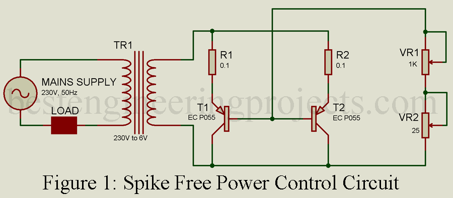
The impedance of the primary winding is varied by varying the effective secondary impedance, which is achieved by the collector-emitter resistance variation. The secondary current is controlled (varied) by varying the resistance ‘R’ between the common bases of transistors T1 and T2, and one terminal of the secondary winding. Resistances R1 and R2 limit the emitter current in the transistors T1 and T2 respectively for safeguard.
By varying resistance R, the bias current in both the transistors is varied, thereby varying the base current of both the transistors. This ultimately varies the collector-emitter resistance of both the transistors in opposite direction, i.e. increases in the base current decrease the collector-emitter resistance increases the overall gain, and vice-versa. This change in the overall secondary resistance causes a similar effective change in the primary impedance (amplified by the factor of (230/6)2 or 8817 times), which is in series with the load, thereby controlling (varying) the power through the load.
As the circuit has no switching action, the RF spikes’ generation is nil. As a result, the waveform across the load is continuous. The circuit gives 90% efficiency and is most suitable for remote power control by keeping the resistance R fitted in a small box at any desired place with a pair of cables.
Check out various other electrical protection circuits posted in the best engineering projects.
- Three-Phase Power Surge Protector Circuit
- Single Phase Preventor with under over-voltage protection.
- Single Phasing Preventor Circuit
- Phase Sequence Change Indicator
Parts list of Spike Free Power Control
| Resistor (all ¼-watt, ± 5% Carbon Unless Stated Otherwise) |
| R1, R2 = 0.1Ω
R = 1KΩ + 25Ω variable resistor |
| Semiconductor |
| T1, T2 = RC P055 (PNP Power Transistor) |
| Miscellaneous |
| T1 = 220V AC to 6V AC step down 2A transformer |