If the system is completely dead, that is nothing happens in the system, you should immediately suspect the power supply. This is one part of any system where the average technician can often find and repair a problem.
Any system is powered by battery or a transformer-rectifier supply connected to the 220-V lines. Batteries usually power portable system. A 9-V battery is most common. To check its output voltage, turn the system on (to load the battery) and measure the battery’s terminal voltage. If it is significantly below 9V, perhaps 8V or less, replace the battery and recheck the unit. Also check for corroded terminals.
Some system employs a group of cells to obtain the necessary voltage. These most be connected in a series-aiding configuration of the positive terminal of one cell to the negative terminal of the next, and so on. The battery compartment has a diagram with battery symbols and plus and minus signs molded into the plastic to help us install the cell properly. Should one cell be placed in the compartment backward, it would cancel the voltage of two cells, thereby dropping the total voltage to the point where the system would not work. Check for proper installation of all cells. Then perform the “loaded” test described above for 9-V batteries.
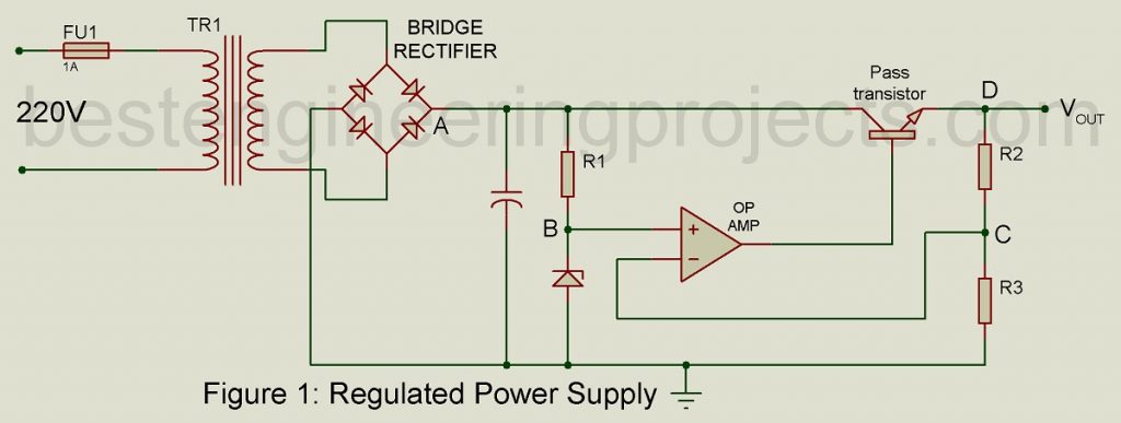
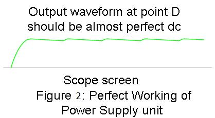
Stereos and communications receivers will most likely use a regulated power supply similar to that shown in figure 1. Start troubleshooting by checking the output voltage with a DMM connected between point D and ground. If the voltage is correct (per manual specs), your problem lies elsewhere. If not, test the fuse for continuity and be sure the power plug is connected to a “hot” outlet and the switch is on. Next, check rectifier output waveform at point A with an oscilloscope per the diagram in figure 2. The waveform should be similar to the one illustrated.
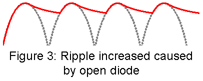
If the rectifier output waveform is not similar to that shown in figure 2, one or more diodes in the bridge have probably failed. Diodes fails in one of two ways, either by opening or shorting. An open diode changes the bridge rectifier from full-wave to half-wave. As a result, ripple increases dramatically (see figure 3). A shorted diode causes heavy currents that should blow the fuse or, at the very least, case overheated components.
Bridge rectifiers are usually encapsulated (you cannot get at the individual diodes). The unit must therefore be replaced should problems be found.
If the filter capacitor (from point A to ground) opens, the bridge output will be unfiltered, making it more difficult for the voltage regulator to eliminate ripple. It’s difficult to say exactly what the waveform would look like; check the maintenance manual for details.
A shorted filter capacitor shorts the rectifier output, causing, at best, a blown fuse, and at worst, a burned-out rectifier and/or power transformer. In either case, open or shorted, replace the capacitor.
Assuming the rectifier and the filter capacitor pass the tests discussed above, measure the zener reference voltage at point B and compare with specs per annual. Measure the voltage at point C, the feedback voltage to the inverting input of the op-amp. It should be within a tenth of the volt or so of the zener voltage. The point C voltage can be calculated using the voltage division formula:
V at point 
Measure the emitter-collector voltage of the pass transistor. It should be approximately 5 to 7 V depending on power supply load. If this voltage is a few tenth of a volt or less, the transistor is shorted and must be replaced.
Note: The above comments on power supply troubleshooting apply for any piece of equipment using a regulated power supply, not just super heterodyne receivers.