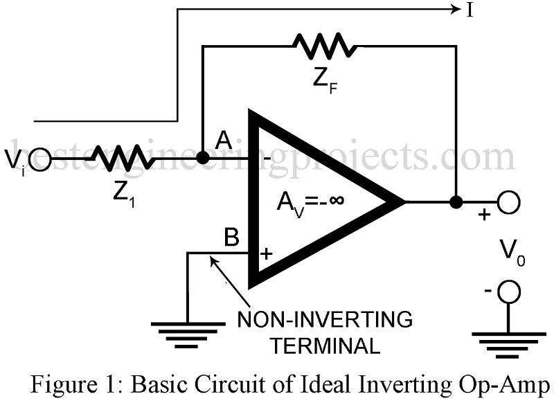
The ideal inverting operational amplifier with voltage shunt feedback from output terminal to the inverting input terminal feedback impedance Zf and with non-inverting terminal grounded configuration is shown is figure 1. 25+ verified electronics projects using op-amp 741.
Description Inverting Operational Amplifier with Voltage Shunt Feedback
This forms the basic inverting op-amp. It is “Inverting” because our signal input comes to the “-” input, and there has the opposite sign to the output. The feedback arrangement used here forms the voltage shunt feedback. Hence as per theory of feedback amplifiers, voltage gain with feedback AVf is given by,
…..(1)
Equation 1 may be established in an alternative way as below:
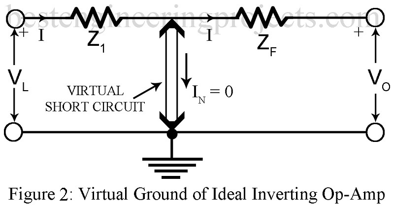
- We make use of Rule I (The output attempts to make the voltage difference between the inputs zero i.e. make Vd zero). Thus, since point B is at ground potential, then as per rule I, point A is also at ground potential. Thus, there exist a virtual ground or virtual short circuit at the input of the Op-Amp indicated by double lines with arrow head in figure 2.
- Using Rule II (The inputs draw no current), no current flows through the input of the Op-amp. This implies that the full current I flows through Zf and nothing is diverted to the input of the Op-Amp.
Hence voltage -IZf across Zf is the output voltage V0 while voltage IZ1 across Z1 is the input voltage Vi. Hence voltage gain AVf is given by,
This agree with equation 1.
What is input impedance?
Now point A is always at zero volt because of the virtual ground. Hence Zin = Z1.
The circuit is known as an inverting amplifier. Its one undesirable feature is the low input impedance, particularly for amplifiers with large closed loop voltage gain where Z1 tends to be rather small. This undesirable feature is remedied in non-inverting amplifier.
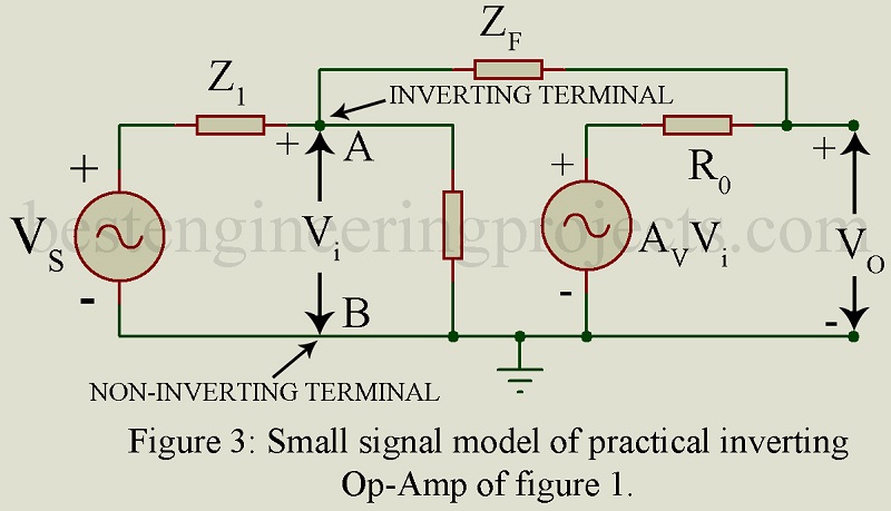
Practical Inverting Op-Amp Equation 1 giving AVf is valid only for infinity voltage gain Av. next we consider a practical inverting Op-Amp shown in figure 3. Here the Op-Amp of figure 1 is replaced by its practical small signal model with ,
and
. Here Av represents the open circuit or unloaded voltage gain.
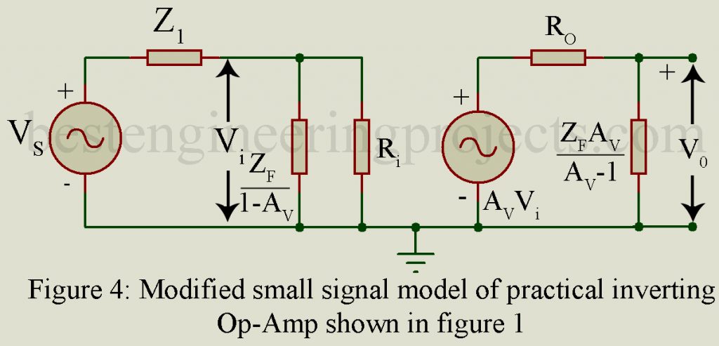
We now apply Miller’s theorem and thereby replace Zf by two impedances, an impedance across the input and an impedance
across the output resulting in the modified model of Figure 4.
Then from Figure 4 we get the following expression for the closed loop gain,
…..(2)
Where is the voltage gain talking into account the loading effect of Zf.
Then AV is given by,
…..(3)
From Equation 3 we note that if R0 = 0 or Yf = 0 (i.e. ), the loading effect of Zf gets removed and AV equal Av. Also as
, |A_V| also tends to infinity and
. Thus, this value of AVf agrees with that given by Equation 1.
The output impedance is very small .
Problem regarding inverting amplifier.
Determine the output voltage for the inverting amplifier shown in figure 1, if (a) vin = 20 mV dc (b) Vin = -50 uV peak sine wave.
Assume that the op-amp is a 741.
- VO = -AVin = -(2)x(105)x(20)x(10-3) = -4000V
This is the theoretical value; the actual value will be a negative saturation voltage of -14V.
- VO = -AVin = -(2)x(105)x(-50)x(10-6) = 10V peak sine wave
This means that the output is a sine wave, since it is less than the output voltage swing of +/- 14V or 28V peak to peak.


