Liquid Crystal Displays (LCD) are activated by an AC signal across s selected display segment; this feature is included in the LCD module itself. In addition to the standard data input, there is also a display frequency input terminal.
The circuit “Multiplexed 4 LCD Display using Arduino UNO” can drive most LCD display. This circuit is used in auto dash board displays, panel meter, wall and table clocks, calculator. In this article we are going to show, how to make 16×8 display using four 16×2 display by using common data lines. The most interesting part of this project is, these display share four data line commonly and displayed different data in each LCD.
Circuit Descriptions of Multiplexed 4 LCD Display using Arduino UNO:
The circuit of LCD Multiplexing is shown in figure 1. This LCD multiplexing circuit accept any 4-bit number and display the letter. The entire circuit of multiplexed display is build around arduino uno board, four LCD display module, four variable and fixed resistors.
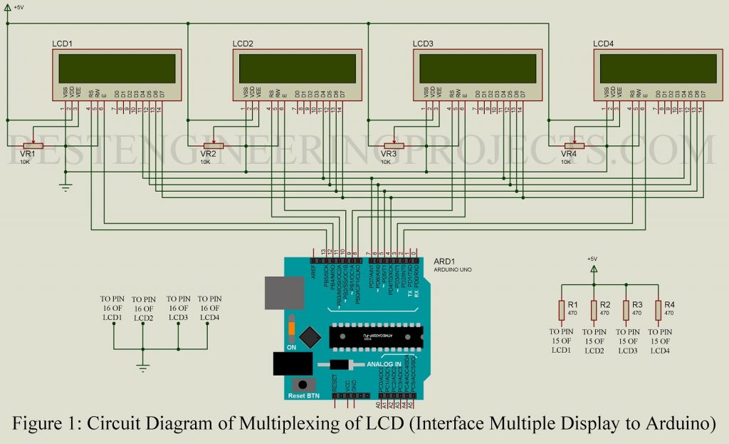
Four LCD interface with arduino uno board in 4-bit data mode. This mode is achieved by connecting higher bit data line of LCD (pin D4, D5, D6 and D7) to digital pin of arduino uno board (pin D7, D6, D5 and D4) respectively as shown in circuit diagram. These four LCD higher bit data line (D4 to D7) share arduino uno pin commonly, but RS pin and EN pin of LCD are connected to different pin of arduino uno board.
You can also use only single LCD by disconnecting the RS and EN pin of al other display. RW pin of all LCD is grounded to perform write operation.
Working of the circuit Multiplexed 4 LCD Display using Arduino UNO
The working functionality of this project is summarized in two points.
- At first, we define all the pins used for LCD i.e. four data line is common for all LCD where RS and EN pin of each LCD is connected to different pins of arduino uno board.
- The data form arduino uno is sent in ASCII format to LCD. When data signal is sent corresponding RS pin of LCD is activated (become high). Thus, it is compulsory to call the appropriate LCD display before displaying data.
Let’s take example to understand this scenario.
When you wish to display Hello in 1st LCD, BestEngineering in 2nd LCD, Projects in 3rd LCD and Arduino in 4th LCD. The only thing you have to do is calling appropriate syntax for appropriate LCD.
|
1 2 3 4 5 6 7 |
lcdA.print(“Hello”); lcdB.print(“BestEngineering”); lcdC.print(“Projects”); lcdD.print(“Arduino”); |
Software Code:
Software code of LCD multiplexing is written in arduino programming language and compiled using arduino IDE. You can directly download the source code from the below link and use it in your system.
Definition of LCD pin
|
1 2 3 4 5 6 7 |
LiquidCrystal lcdA(13,12,7,6,5,4); LiquidCrystal lcdB(11,10,7,6,5,4); LiquidCrystal lcdC(9,8,7,6,5,4); LiquidCrystal lcdD(3,2,7,6,5,4); |
As we can see from above code, only RS and EN pin is connected to individual pin where all the data line of LCD is connected to arduino pin commonly.
Arduino Code:
|
1 2 3 4 5 6 7 8 9 10 11 12 13 14 15 16 17 18 19 20 21 22 23 24 25 26 27 28 29 30 31 32 33 34 35 36 37 38 39 40 41 42 43 44 45 46 47 48 49 |
#include <LiquidCrystal.h> LiquidCrystal lcdA(13,12,7,6,5,4); //pin definition for LCD 1 LiquidCrystal lcdB(11,10,7,6,5,4); //pin definition for LCD 2 LiquidCrystal lcdC(9,8,7,6,5,4); //pin definition for LCD 3 LiquidCrystal lcdD(3,2,7,6,5,4); //pin definition for LCD 4 void setup() { lcdA.begin(16,2); //Initializes of LCD 1 lcdB.begin(16,2); //Initializes of LCD 2 lcdC.begin(16,2); //Initializes of LCD 3 lcdD.begin(16,2); //Initializes of LCD 4 } void loop() { lcdA.setCursor(0,0); lcdA.print("3 16x2 LCD Using"); delay(100); lcdB.setCursor(0,0); lcdB.print(" Designed By-> "); delay(100); lcdC.setCursor(0,0); lcdC.print("Visit Website"); delay(100); lcdD.setCursor(0,0); lcdD.print("BestEngineering"); delay(100); lcdA.setCursor(0,1); lcdA.print("Single Arduino"); delay(100); lcdB.setCursor(0,1); lcdB.print("Krishna Keshav"); delay(100); lcdC.setCursor(0,1); lcdC.print("and Subscribe"); delay(100); lcdD.setCursor(0,1); lcdD.print("Projects"); delay(100); } |