Many of us use water pumps for drawing water from an underground tank. Whenever the water level in the tank goes low we have to switch ‘off’ the motor and when it reaches a high level we have to switch ‘on’ the motor. The circuit automatic suction tank motor controller given here solves this problem. The truth table for the digital circuit of automatic suction tank motor controller Condition H L Y Remark Empty tank 0 0 0 Water is filled up to ‘L’ 0 1 0 Full tank 1…
Read MoreCategory: Electronics Projects
1/86400 Hz Frequency Ganerator Circuit
The circuit 1/86400 Hz frequency generator provides one clock pulse every 24 hours from a 1 Hz input clock pulse source, which is commonly available through a digital clock. It can be used to provide am/pm indication in those digital clocks which do not have this facility, or it may be utilized to advance the date of an electronic calendar every day. It can also be used to trigger an alarm at a determined time without fail. Circuit Description of 1/86400 Hz Frequency Generator The present circuit 1/86400 Hz frequency…
Read MoreLight and Touch Operated Music Door Bell
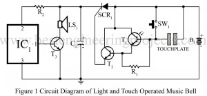
The novel circuit light and touch operated music bell used a photo transistor (T1) with an npn transistor in emitter-follower mode to increase sensitivity of the circuit. So even if very little light fall on the photo transistor, it gives a triggering pulse to SCR gate and the SCR starts conducting. Circuit Description of Light and Touch Operated Music Bell When SCR conducts, IC UM66 starts producing music. After the music has halted, no current flows through the SCR and the SCR switches off till the light falls again on…
Read More12 Tones Doorbell
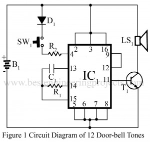
Every day addiction of people towards technology is growing deeper and deeper, even before entering into someone’s house we press doorbell which is a clear example to support our belief. Listening same doorbell always might be boring, this circuit 12 tones doorbell help us to avoid this dull situation. Music doorbells, music horns, touch-sensitive doorbells, etc are not new projects electronics hobbyists, especially for BEP readers. But, this music producer (twelve popular tones in sequences) gives a new dimension to musical doorbells. Whenever a switch is pressed, a popular tone…
Read MoreAutomatic Light Operated Switch using LDR and IC741
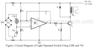
Along with modernization, people are more prone to the comfort zone. Several inventions have been made to meet this requirement. Following the same trend, here we have presented a simple circuit; automatic light operated switch using LDR and IC741. People are busy, every second has a vital role in our busy schedule. Why shall we waste our valuable time turning on every switch in the building? The situation turns more troublesome when one needs to reach the ground floor just because it’s getting dark and s/he needs to turn on…
Read MoreFour channel audio mixer
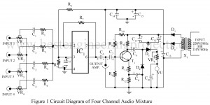
As per the name of the circuit, it is clear that this circuit connects four different audio signals as one. So, it is call four channel audio mixer. Here is that simple circuit; “four channel audio mixer” using op-amplifier 741. It is to be noted in the circuit that the op-amplifier 741 works here as an inverting amplifier. Circuit Description of four channel audio mixer: The circuit of four channel audio mixer is wired around op-amp IC 741 followed by few other active as well as passive components. The IC 741…
Read MoreFrequency Counter Using Digital MultiMeter
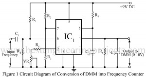
As being electronic hobbyists we love to design and verify various types of circuits, we often have to measure the output frequency. The device which is used for this purpose is called the frequency counter. A frequency counter is an electronic device that measures the frequency of electric and electronic circuits by counting clock pulse. The frequency counter available in markets is quite expensive and sometimes we cannot afford it. In BEP LAB we designed and verified a circuit called “Frequency Counter Using Digital MultiMeter” which will serve as an…
Read MoreCrystal controlled inverter | Verified Inverter Circuit
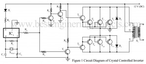
Many Inverter Circuits have already been posted on many other websites. The inverter circuit “Crystal Controlled Inverter” presented here provides a stable output frequency even when there is a change in the DC voltage applied to the inverter. This stable output of the Crystal control Inverter is obtained from the 3.2786 MHZ crystal (XTAL1). You can also make your 3000W inverter using a microcontroller. Circuit Description of Crystal Controlled Inverter. The Inverter circuit “Crystal Controlled Inverter” is built around popular flip flop IC MM 5369 (IC1) followed by a few…
Read MoreA versatile Decibel Meter Circuit
A decibel meter is an instrument to measure levels of the input signal(s) in decibel units. The main areas of application of decibel meter are audio level indicators, record level indicators, spectrum analyzers, and the like. The project “A versatile decibel meter circuit” shows here provides a resolution of 20 steps. Although the steps are linear, they are calibrated with corresponding decibel value so that it suits most of the requirement. Description of Versatile Decibel Meter Circuit The schematic diagram of the versatile decibel meter circuit is shown in figure…
Read MoreElectronics Washing Machine Control | Circuit Diagram
Nowadays, commercially available washing machines are provided with features like the auto-off timer, reversible impeller, etc. Most of them have mechanical timers, reverses, etc. Some are equipped with electronic timers. But they are very expensive and out of reach of the average consumer. Electronic Washing Machine Control circuit provides all the facilities provided by reputed companies and even more. The circuit has a timer circuit that can be set to any duration from 0 to 15 minutes and can be extended to any length of time by merely changing a…
Read More

