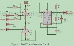
A single beam CRO can be used for simultaneous display of two signals using this simple circuit “Dual Trace Generator Circuit”. The circuit uses one NE555 and two LM741 ICs, besides some passive components. The diode (1N4148) is used to get a 50 percent duty cycle. Circuit Description of Dual Trace Generator Circuit IC 555 is connected in astable mode and acts as a self-switching analog switch between the two signals to be displayed on the CRO. The output of IC 555 is given to the CRO. In order to…
Read MoreCategory: IC 741 Based Projects
Mini Projects using IC 741
Here in this post, we have compiled some of the verified mini projects using IC 741. The mini-projects using IC 741 listed here can be used as diploma-level as well as high school-level projects. List of Mini Projects using IC 741 1. Electronics Thermometer Using Op-amp 741 IC Here is the circuit diagram of an electronics thermometer using an operational amplifier and silicon diode having a range of -20oC to 125oC.2. Electronic Fuse Using Op-amp 741 Here is an electronic fuse using op-amp 741 which features slow-blow properties, a…
Read MoreElectronics Thermometer Using Op-amp 741 IC
Here is the circuit diagram of an electronics thermometer using op-amp 741 IC and a silicon diode having a range of -20oC to 125oC. Various types of temperature measuring and controlling circuits either using a microcontroller or discrete component are already posted on bestengineeringprojects.com. Circuit Diagram of Electric Thermometer Using OP-AMP 741 The entire circuit of the electric thermometer is built around two op-amp 741 IC, a silicon diode, and a few passive components, where silicon diode D1 is used as a temperature sensor. The diode 4148 has a voltage…
Read MoreElectronic Fuse Using Op-amp 741
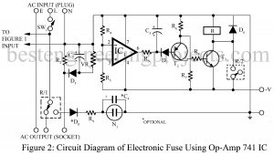
Here is an electronic fuse using op-amp 741 which features slow-blow properties, a variable current limit, and a ‘live’ indication of its operation. Moreover, it is simple to restore. The electronic fuse using op-amp 741 allows the gadget to draw a higher current initially but keeps a watch on it. if the gadget continues to draw more current beyond the set time limit, it disconnects the supply. The fuse, therefore, acts as a cut-out and indicates this by a neon glow. It is replaced by simply resetting the circuit once.…
Read MoreSound detector circuit using op-amp 741
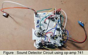
The circuit diagram of the sound detector circuit using op-amp 741 is shown in figure 1. The heart of the circuit is op-amp 741 which is used in order to sense the vibrations of sound waves condenser microphones. Introduction of Sound detector circuit using op-amp 741 Sometimes due to lack of concentration and our ignorance, we are unable to hear anything around us. And, that could lead to unfortunate misfortunes which could have been avoided with appropriate precautions. This circuit called ‘Sound Detector’ is what detects vibrations of the sound waves…
Read MoreSound Operated Intruder Alarm with Flash
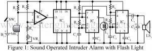
Sound Operated Intruder Alarm with extra features like a flashlight, circuit diagram, description with working principle, and parts list. Introduction to Sound Operated Intruder Alarm with Flash If you have already gone through the previous project Op-amp 741 Based Sound operated Light on our website, then for you this project is a transformation of that generalized project into a specialized intruder’s alarm project. Why should one invest much effort, time, and money to recreate a new circuit when a slight modification to the existing project works fine? This is the core…
Read MoreBass Booster Circuit using Op-Amp 741 IC
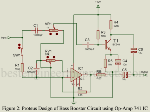
Here is one another basic project call bass booster using op-amp 741 IC. The circuit bass booster increases beat frequency without affecting high frequency. Description of Bass Booster Circuit using Op-Amp 741 IC The circuit of bass booster shown in figure 1 is divided into two main section i.e. bypass high frequency and boost section. The input of this circuit is connected to the output of pre-amplifier circuit and it’s output to input of power amplifier circuit. When audio signal is given to the input, high frequency is passed through…
Read MoreDIY Headphone Amplifier using 741 IC
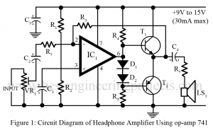
Various type of amplifier and pre-amplifier circuit has appeared in this website in amplifier and pre-amplifier section. The circuit posted here is of DIY headphone amplifier which is suitable for headphone or 8-ohm speaker or more impedance. The circuit is so designed that it has no risk of overloading or distortion of either the circuit or headphone. Circuit Description DIY Headphone Amplifier using 741 IC The heart of the circuit headphone amplifier is op-amp 741 which provide suitable gain where the transistor T1 and T2 are used to drive low…
Read MoreElectronic Thermometer Circuit
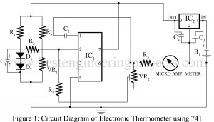
A number of measurement circuits have appeared on this website. The project posted here is of Electronic Thermometer Circuit using op-amp 741. This circuit is suitable to measure temperature from 00C to 500C using a linear scale am-meter. The range can be extended up to 1000C using 100 microamperes. Circuit Description of Electronic Thermometer Circuit using 741 IC The circuit is self-explanatory for the experienced hobbyist and performs its task with a minimum number of components. The operational amplifier is used in compactor mode. The diodes D1 and D2 are used…
Read MoreHigh/Low Voltage Cut-out Using Op-Amp 741
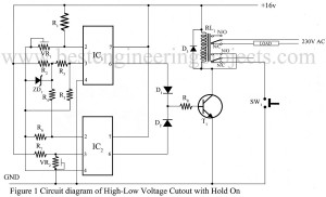
Ever had that mini heart attack when the lights flicker, and you wonder if your expensive appliances just took a hit? Electricity, unpredictable as a summer thunderstorm, can be a blessing or a curse. One moment it’s steady as a rock; the next, it’s spiking like a roller coaster. That’s where a voltage cut-out circuit steps in—your personal guardian angel against electrical bedlam. Why This Circuit Matters Imagine your refrigerator humming happily along. Out of nowhere, a voltage spike bursts in like an unwanted house guest. Your trusty refrigerator can…
Read More