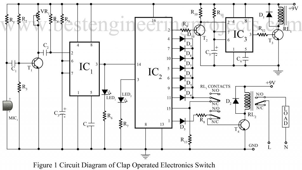
The clap switch circuit is not a new idea for the electronics hobbyist. Previously we had posted a simple clap-operated switch. Now, here is a clap switch circuit using 555, used to control any appliance by clapping five times. We used here decade counter for the right clap code i.e. only the right clap activates the appliance (five claps within the preset time interval of 10 seconds).
Description of Clap Switch Circuit Using 555
The clap switch circuit using 555 is built around timer IC 555, decade counter IC CD 4017, a few transistors, MIC, and a few passive components.
The MIC1 (condenser microphone) is used here as a sensor, senses the clap sound, and further convert it into an electrical signal. The output electrical signal from MIC1 is so weak that it needs amplification; this work is done by transistor T1. The amplified output from the collector of transistor T1 is given to pin 2 of IC1 (NE555), configured in monostable mode.
The trigger from the amplifier produces a clock pulse at the output of pin 3 of IC1. Glowing LED1 indicates the clock pulse at output pin 3. The output from pin 3 of IC1 is given to clock pin 14 of decade counter IC2 (CD4017). Firstly, when the power is given to the clap switch circuit, the output from pin 3 is high and glow LED2, glowing LED2 indicates that the switch is ready for use. At this time all other outputs of the clap switch circuits are low. The output from pin 1 is used for activating the appliance via relay RL2.
At each clock (generated from each clap), the output of IC2 gets incremented. The output from pin 2 of IC2 is used to activate IC3 configured in monostable mode. The output from pin 3 of IC3 is used to drive relays through a driver circuit build around transistor T3.
IC3 acts as a monostable multivibrator (timer) with a period of approximately 10 seconds, which provides a delay time to turn on an appliance even after completing the five claps before the preset time of 10 seconds. The reset pin 15 is connected to contacts of relay RL1 for the preset time of 10 seconds.
Check out other clap switch and sound operated circuits posted in bestengineeringprojects.com
- Clap Switch Cum Touch Switch
- Clap Switch Circuit
- Sound Operated On-Off Switch
- Sound Operated Intruder Alarm with Flash
- Op-Amp 741 Based Sound Operated Light
When all the five claps are applied within 10 seconds, the outputs at pin 1 of IC2 go high and relay RL2 is energized to turn on the appliance just after the de-energization of relay RL1. Table 1 shows the On/Off condition of the appliance for every clap. In the wrong clap code, the high output of IC2 reset it via its pin 15 and the appliance doesn’t turn on.
TABLE 1
|
On/OFF status of the appliance for every clap |
||||
|
Claps |
Relay 1 (RL1) |
Relay 2(RL2) |
LED2 |
Appliance Status |
|
1 |
Energized |
De-energized |
Off |
Off |
|
2 |
Energized |
De-energized |
Off |
Off |
|
3 |
Energized |
De-energized |
Off |
Off |
|
4 |
Energized |
De-energized |
Off |
Off |
|
5 |
Energized |
De-energized |
Off |
Off |
|
6 |
Off |
Off |
On |
Off after 10 seconds |
PARTS LIST OF CLAP SWITCH CIRCUIT USING 555
|
Resistor (all ¼-watt, ± 5% Carbon) |
|
R1 = 10 KΩ R2 = 470 KΩ R3 = 100 KΩ R4, R5, R11 = 1 MΩ R6 = 220 Ω R7 = 470 Ω R8, R9, R12 = 1 KΩ R10 = 22 KΩ R13 = 150 KΩ VR1 = 1 KΩ |
|
Capacitors |
|
C1, C2 = 0.1 µF (Ceramic Disc) C3 = 1 µF/16V (Electrolytic Capacitor) C4, C6 = 0.01 µF (Ceramic Disc) C5 = 10 µF/16V (Electrolytic Capacitor) |
|
Semiconductors |
|
IC1, IC3 = NE555 (Timer IC) IC2 = CD4017 (Decade Counter IC) T1 = BC549 (NPN Switching and amplifier transistor) T2 – T4 = BC548 (general-purpose NPN bipolar junction transistor ) D1, D2 = 1N4007 (Rectifier Diode) D3 – D10 = 1N4148 (Small Signal Switching Diode) |
|
Miscellaneous |
|
RL1 = 9V, 150Ω, 2C/0 Relay RL2 = 9V, 150Ω, 1C/0 Relay MIC1 = Condenser Microphone LED1, LED2 |

please help me …anybody i want to submit the project ..im in `12th std ..stream electronics anybody please help me out …
What kind of help do you need?