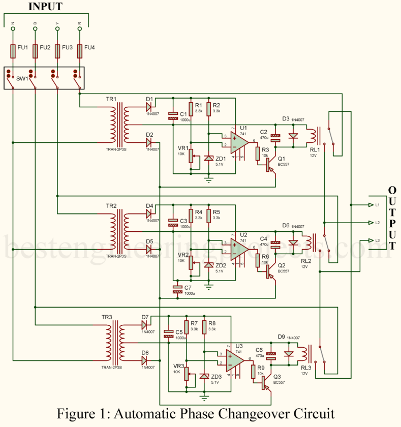
The most important feature in a three-phase electrical system is that the supply of power to critical equipment must not be interrupted, especially at places where voltage fluctuations are common. The practical solution for this problem is an automatic phase changeover circuitry. It enables the equipment to smoothly switch to another phase in case one or more phases have low voltage, thereby ensuring a continuous power supply. In this article, we explain how an automatic phase changeover circuit works, what its main components are, and how you can build a suitable one for your application. For more details on measuring phase voltages, see Three-Phase AC Voltage Measurement Using Arduino, or add extra protection with this Three-Phase Power Surge Protector Circuit.
What is an Automatic Phase Changeover Circuit?
The automatic phase changeover circuit is the one capable of noticing voltage drops or an outage in any of the three phases of a power supply and then automatically switches the load to other available phases. In other words, what this is trying to imply is that it ensures your equipment receives appropriate voltage, even if one of the phases fails due to very low voltage.
Key Features of the Circuit
- Automatic phase selection: circuit automatically switches to an available phase if the voltage on any one phase falls below a threshold.
- Low Voltage Protection: The protection module will protect the equipment against the influence of low voltage operation, since operating under such conditions may result in damage or inefficiency.
- Continuous Power Supply: Keeps your equipment running by switching to another phase if one or two phases experience low voltage.
How the Circuit Works
This automatic phase changeover circuit consists of three identical sections for monitoring one of the phases: R, Y, or B. The working of this simple circuit is as follows:
- Voltage Monitoring: Each phase is stepped down, with the help of a transformer, to a comfortable level of 12V AC. The stepped-down voltage is then rectified using diodes and filtered through to produce a stable DC voltage that can be fed into the comparator circuit.
- Comparator Circuit: Each section has an operational amplifier LM741 arranged in the configuration of a comparator. The voltage divider network decides the input voltage to the comparator. A Zener diode, on the other hand, provides a stable reference voltage of 5.1V. As long as the incoming phase voltage is higher than the minimum acceptable threshold levels (ideally between 200 V to 230 V), the comparator output stays high, thus keeping the relay de-energized.
- Relay Switching: If the phase voltage falls below the reference threshold of 200V, then the output from the comparator goes low, conduction the connected transistor to energize the relay. The relay disconnects the load from the faulty phase and connects it with another phase giving sufficient voltage. In this way, the load is guaranteed continuous power.
Example Operation for a Single Phase (R Phase)
- When the voltage in phase R is within the acceptable range (200V-230V), the comparator output is high, and the relay remains de-energized. The load is connected to phase R through the normally closed contact of the relay.
- If the voltage in phase R drops below 200V, the comparator output goes low, the relay energizes, and the load is switched to another phase (such as Y or B) that has adequate voltage.
Components Required for Automatic Phase Changeover Circuit
Resistors (all ¼-watt, ± 5% Carbon unless stated)
R1, R2, R4, R5, R7, R8 = 3.3kΩ
R3, R6, R9 = 10kΩ
VR1, VR2, VR3 = 10kΩ
Capacitor
C1, C3, C5, C7 = 1000µF/35V electrolytic
C2, C4, C6 = 470µF/35V electrolytic
Semiconductor
D1, D2, D3, D4, D5, D6, D7, D8, D9 = 1N4007
ZD1, ZD2, ZD3 = 5.1V Zener diode
U1, U2, U3 = 741 Op-Amp
Q1, Q2, Q3 = BC557
Miscellaneous
TR1, TR2, TR3 = 230V AC Primary to 12V – 0V – 12V, 300mA Sec. Transformer
RL1, RL2, RL3 = 12V, 1C/O Relay
FU1, FU2, FU3, FU4 = 5Amp. Fuse
Practical Considerations
- Fuse Protection: Each phase of a circuit should have a fuse to permit protection against overcurrent conditions. The load connected shall not exceed the rating of the fuse.
- Relay Rating: Specify application switches using relays rated to safely handle the current requirements of your equipment.
- Enclosure and Wiring: The transformer and the relays must be mounted on an appropriate enclosure, and then wiring should be done with good-quality, insulated copper wire for safety and reliability.
Advantages Using This Circuit
- Low Voltage Protection: This will prevent the equipment from low voltage and saving them from damage, thus improving the poor performance of the connected devices because of low voltage.
- Continuity of Power: Switches over to a healthy phase without interruption to the operation of critical equipment.
- Simple and inexpensive: this is a very inexpensive circuitry for applications requiring critical continuation of power.
Safety Tips
- Always use connections through good quality insulated copper wires.
- Ensure the circuit is appropriately grounded to avoid electrical hazards.
- Employ correct ratings of relays and fuses that can allow matching current requirements of your equipment.
Conclusion
It is a continuous power supply in three-phase systems where changes are very common, especially in areas where voltage fluctuations occur frequently. By automatically switching to a phase with the correct voltage, this circuit prevents damage to your equipment and ensures smooth operation. With the right components and careful assembly, you can build this circuit to enhance the reliability of your power supply system.
Additional Resources
For single-phase protection, explore the Single Phase Preventer with Under/Over Voltage Cutout.

Thank you. Great job always.