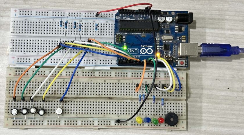
Have you ever had one of those moments where you’re competing with friends and wish there was a fun way to see who got the fastest reflexes? Here’s your answer: an Arduino-based Fastest Finger First game with LEDs! There are no complex displays, no 7-segment numbers to deal with—just good ol’ LEDs lighting up for the winner and a dedicated reset button to start fresh.
If you’re a fan of simple yet engaging DIY projects, this one will light up your world—literally and figuratively. So, let’s dive in!
What’s This All About?
Imagine four friends sitting around, itching to prove who has the quickest reflexes. You press your Button, and BAM! Your LED lights up faster than anyone else’s. It’s simple, clean, and oddly satisfying—no fiddling with displays or alarms, just LEDs and a button for each contestant.
Oh, and did I mention? There’s a reset button for the referee to keep things fair. One push, and everyone’s back to square one. It’s like hitting the “new game“ button in life.
What You’ll Need
Let’s start with the shopping list—nothing too fancy here:
- 1 Arduino Board (Uno is perfect, but any will do)
- 4 Push Buttons (for contestants)
- 4 LEDs (to represent each contestant)
- 1 Reset Button (to start over after each round)
- Resistors:
- 4 x 10kΩ (pull-down resistors for the buttons)
- 4 x 220Ω (current-limiting resistors for the LEDs)
- Jumper Wires and a Breadboard
- A Buzzer (optional, for extra flair)
Have you got those? Great. Let’s build.
How It Works
Think of this project as a mini referee. The Arduino sits in the middle, watching all the buttons. The moment someone presses theirs, the game freezes, their LED lights up, and nobody else can “buzz in.” It’s like the Arduino yells, “STOP! We have a winner!”
But wait—what if somebody accidentally presses his Button during setup? Or perhaps you just want to play another round? That’s where the reset button comes in. One press, and it’s like nothing ever happened: a clean slate ready for action.
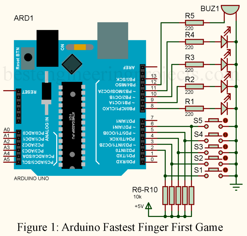
The Circuit Diagram Arduino Fastest Finger First Game
Don’t let the word “circuit” intimidate you. It is as easy as coloring in dots on a coloring book.
- Connect the Buttons: Each Button gets one leg connected to a digital pin on the Arduino (say, pins 2, 3, 4, and 5). The other leg goes to GND.
- Pull-Down Resistors: Add a 10kΩ resistor between each Button’s pin and GND to stabilize the signal. Nobody likes a jumpy circuit.
- Hook Up the LEDs: Connect each positive leg to a digital pin (pins 8, 9, 10, and 11). The negative leg gets a 220Ω resistor and then goes to GND.
- Add the Reset Button: The reset button goes to pin 6, with a 10kΩ pull-down resistor, just like the others.
- Optional Buzzer: Hook it up to pin 12 with a 220Ω resistor in series.
The Code
Here’s where the magic happens. Paste this code into the Arduino IDE, upload it, and prepare to play.
|
1 2 3 4 5 6 7 8 9 10 11 12 13 14 15 16 17 18 19 20 21 22 23 24 25 26 27 28 29 30 31 32 33 34 35 36 37 38 39 40 41 42 43 44 45 46 47 48 49 50 51 52 53 54 55 56 57 58 59 60 61 |
// Define button pins const int buttonPins[] = {2, 3, 4, 5}; // Buttons for each contestant const int ledPins[] = {8, 9, 10, 11}; // LEDs for each contestant const int buzzerPin = 12; // Optional buzzer pin const int resetButtonPin = 6; // Reset button pin bool buttonPressed[4] = {false, false, false, false}; // Track button states bool winnerDeclared = false; // Flag to check if a winner is declared void setup() { // Initialize button pins as inputs with pull-down resistors for (int i = 0; i < 4; i++) { pinMode(buttonPins[i], INPUT_PULLUP); pinMode(ledPins[i], OUTPUT); digitalWrite(ledPins[i], LOW); // Turn off LEDs initially } pinMode(buzzerPin, OUTPUT); digitalWrite(buzzerPin, LOW); // Turn off buzzer initially // Initialize reset button pin as input pinMode(resetButtonPin, INPUT_PULLUP); } void loop() { if (!winnerDeclared) { for (int i = 0; i < 4; i++) { if (digitalRead(buttonPins[i]) == LOW) { // Check if button is pressed buttonPressed[i] = true; declareWinner(i); // Declare the winner break; // Exit the loop } } } // Check for reset button press if (digitalRead(resetButtonPin) == LOW) { resetGame(); } } void declareWinner(int winner) { winnerDeclared = true; // Turn on the winner's LED digitalWrite(ledPins[winner], HIGH); // Sound the buzzer (optional) digitalWrite(buzzerPin, HIGH); delay(500); // Buzzer sound duration digitalWrite(buzzerPin, LOW); } void resetGame() { // Turn off all LEDs for (int i = 0; i < 4; i++) { digitalWrite(ledPins[i], LOW); buttonPressed[i] = false; } winnerDeclared = false; } |
How to Play
- Power up your Arduino.
- Gather your contestants (and maybe a judge to press the reset button).
- On “GO!”, each contestant hits their Button as fast as possible.
- The fastest player’s LED lights up, declaring them the winner.
- Press the reset button, and you’re ready for another round.
Why This Version Rocks
- Simple Yet Fun: Who needs complicated displays when LEDs do the job beautifully?
- Reset Button: Adds a human touch—like blowing the whistle to start over.
- Customizable: Want more buttons? Add them! Fewer LEDs? Easy peasy.

Wrapping Up
This humble project is more than fun, but rather a door to the world of electronics and programming. If the activity of doing it with your friends feels great, or showing off your skills, or just playing for fun, this can’t be resisted in the Arduino Fastest Finger First Game.
So, what’s keeping you behind? Power up your Arduino, light those LEDs on, and let the fastest win. What’s more important is that you’d have to share your version of this project, for the rest of the world deserves to see your genius.

The diagram shows R6-R10 as Pull-up resisters, but the code refers to Pull-down resisters?
Thank you for your observation! There is no reference to pull-down resistors in the code; the software explicitly uses pull-up resistors through the INPUT_PULLUP configuration in the pinMode() function. This activates the Arduino’s internal pull-up resistors, ensuring the pins are held high by default and pulled low when the button is pressed.
The external pull-up resistors (R6-R10) shown in the diagram are not strictly necessary because the internal pull-up resistors provided by the Arduino can fulfill the same role. If you are using the external pull-up resistors as shown in the diagram, you can configure the pins as INPUT instead of INPUT_PULLUP to avoid redundancy.
In summary:
The code uses internal pull-up resistors (INPUT_PULLUP), not pull-down.
External pull-up resistors (R6-R10) can be removed unless you have specific reasons for including them in your circuit design.
Let us know if you have further questions or need clarification!