In this article we will discuss about different applications of Ferrites.
Applications of Ferrites
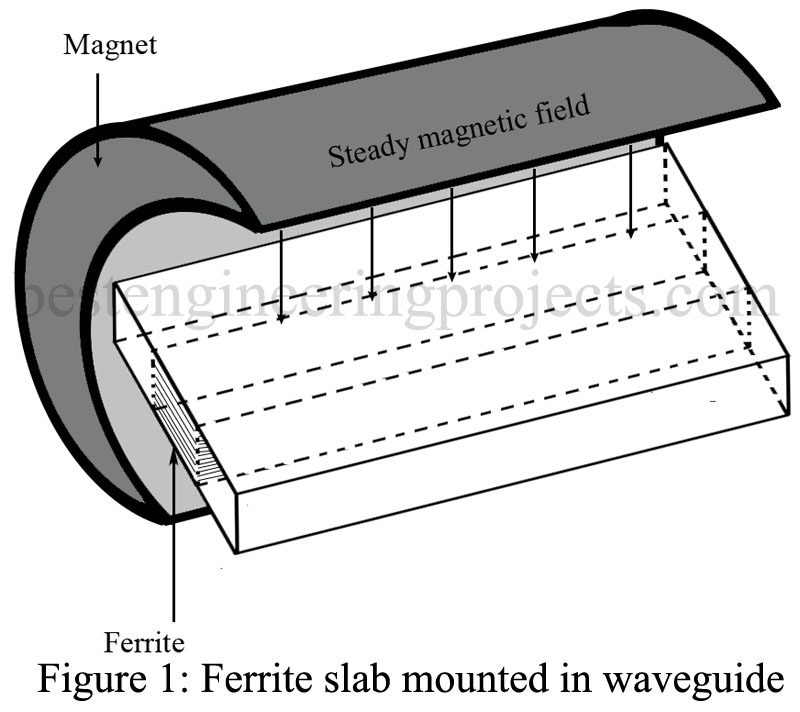
ATTENUATOR: One application of ferrites is as an attenuator. Figure 1 shows a piece of ferrite placed in the center of a waveguide; a steady magnetic field is applied as shown. This arrangement will attenuate frequencies at the resonant frequency of the electrons in the ferrite, whereas other frequencies will be attenuated very slightly. Changing the strength of the dc field produces a change in the frequency that will be attenuated, although this occurs over a limited range.
The dc field is produced by current flowing through a coil wound around the waveguide. The strength of the field, which depends on the current flowing through the coil, determines the frequency of precession. Usually, the ferrite attenuator is in the form of an adjustable vane of ferrite extending into the waveguide. The farther the vane extends into the waveguide, the greater the attenuation, since more of the RF energy must travel through the ferrite.
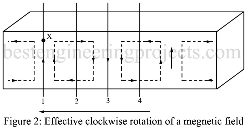
ISOLATOR: Another application of ferrites is that of an isolator. When used as an isolator, the ferrite allows energy to travel in one direction but absorbs energy traveling in the opposite direction. Figure 2 depicts an electromagnetic wave traveling from right to left. It illustrates how the wave, at a point off the centerline of the guide, will appear as a rotating magnetic field. At one instant shown in Fig. 2, the magnetic field at point is pointed up. When the magnetic field at point 2 reaches point X, the magnetic field will be directed to the right. When point 3 reaches X, the magnetic field is downward, and when point 4 on the wave arrives at X, the field is directed to the left.
Thus, as the wave passes point X, the magnetic field appears to rotate in a clockwise direction. At any point off the center of the waveguide, the magnetic field will appear to rotate as the electromagnetic wave passes. This same analysis can be used to show that with a wave traveling from left to right the magnetic field appears to rotate counterclockwise at point X.
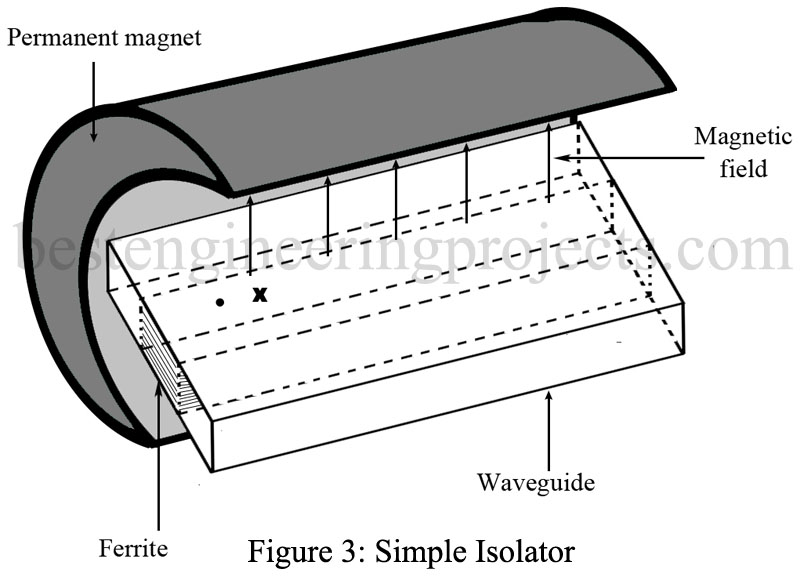
Now let us place a section of ferrite in the waveguide at X. This is shown in Fig. 3, which illustrates a simple isolator consisting of a piece of waveguide, a permanent magnet, and a section of ferrite. The ferrite’s electron resonant frequency and the microwave frequency are made the same by changing either the magnetic field strength or the microwave frequency. When the frequencies are the same, a wave traveling from left to right in the waveguide produces a rotating force in the direction of the natural precession of the electrons in the ferrite. The amplitude of precession increases, taking power from the electromagnetic wave. This power is dissipated as heat in the ferrite.
A wave that is traveling from right to left in this waveguide acts as a rotating force in the electrons to oppose the natural precession. This will not increase the amplitude of the precession, and energy is not absorbed from the electromagnetic field. About 0.4-dB attenuation takes place in a wave traveling from right to left, but as much as 10-dB attenuation occurs in a wave traveling from left to right.
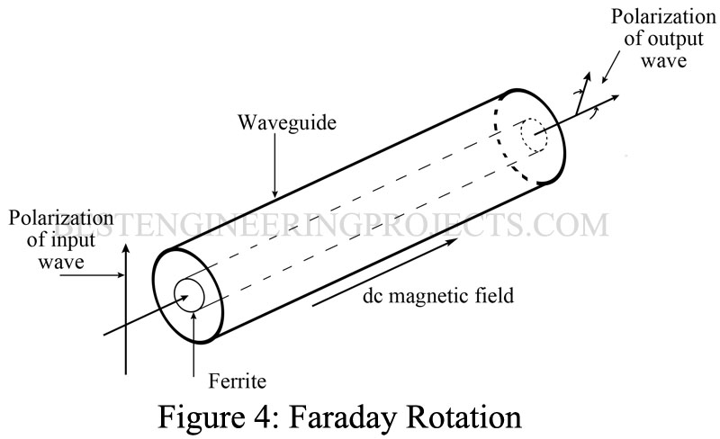
FARADAY ROTATION: Another effect takes place when microwaves are passed through piece of ferrite in a magnetic field. The plane of polarization of the wave is rotated if the frequency of the microwave is above the resonant frequency of the ferrite electrons. This is known as the Faraday rotation effect. When RF energy enters the ferrite material, the magnetic moment of the electron precesses as usual but at a frequency different from the RF. The H lines within the ferrite now are the resultant produced by vector addition of the rotating magnetic moment and the RF field. A new RF field, which is rotated from the original RF field, results. The amount of rotation is determined by the dc magnetic field and the length of the ferrite.
Figure 4 shows a ferrite rod that is placed lengthwise in the waveguide. The dc magnetic field is set up by a coil. Now assume that a wave that is vertically polarized enters the left end of the waveguide. As it enters the ferrite section, it will set up limited precession motion of the electrons. The interaction between the magnetic fields of the wave and the precessing electrons rotates the polarization of the wave. With the correct dimensions of the ferrite rod, the wave is polarized at a 45° angle from the original. Different dimensions of the rod and magnetic field strengths produce other shifts in polarization.
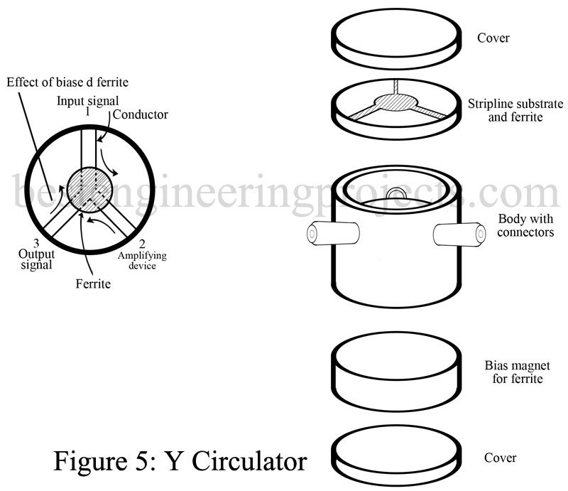
CIRCULATOR: Two-terminal amplifying devices require a means of isolation between input and output power. A circulator is a ferrite device that is the commonly used solution to that problem. The most popular type of circulator is the Y circulator shown in Fig. 5.
Y circulators come in waveguide, coaxial line, or microstrip versions, with the latter shown in Fig. 5. With the three lines arranged 120° apart as shown, energy coupled into arm 1 goes only to arm 2, while 2 feeds only 3 and 3 feeds only 1. The ferrite provides the correct rotational shift to provide this operation.
OTHER FERRITE APPLICATIONS: Ferrites find application in many non-microwave applications. They are widely used in portable radio antennas as the core for a winding IF transformer cores, TV fly-back and deflection coil cores, magnetic memory cores in outers. Another application to the communications field is ferrite bead. It is a small bead of ferrite material with a hole through its center such that it can be threaded onto the wires of an electronic circuit. Its effect is to impedance to dc and low frequencies but a relatively high impedance to radio frequency are widely used as inexpensive replacements for radio-frequency chokes (RFC) to obtain effective RF decoupling, shielding, and parasitic suppression without an attendant sacrifice in dc or low-frequency power.
A ferrite bead on a conductor and its inductive effect are shown in Fig. 6. As the unwanted high frequency flows through the conductor, it creates a magnetic field around the wire. As the field passes into the ferrite bead, the higher (than air) permeability of the bead causes the local impedance to rise and create the effect of an RFC in that location.
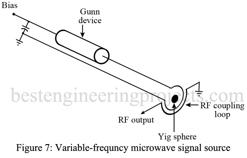
Since ferrite materials are able to attenuate specific microwave frequencies, they are being used for filter applications in place of resonant cavities. The highest-Q ferrite filters are the yig materials. These filters offer small size and electronic (magnetic) tuning advantages over the resonant cavities but are not as high-Q in response. Yig filters are commonly used with the Gunn or IMPATT devices in electronically controlled solid-state microwave sources, as shown in Fig. 7. The electromagnet that controls the frequency has been omitted in the figure but must surround the yig sphere shown. The output energy is taken by the RF coupling loop shown. The simplicity of this variable frequency microwave source is apparent from the figure.
