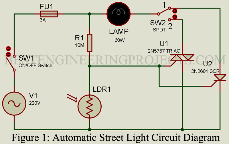
The article automatic street light circuit diagram is self-sensing fully automatic night lamp designed to work with AC. Unlike other circuit it does not require DC thus no rectifier and bulky capacitor and as a result making cost will be cheap. One can use this circuit with street light, dome lamp, parking light etc. this simple circuit switch on the light at night and off automatically at day time.
Description of Automatic Street Light Circuit Diagram
This simple project is built around four common available components i.e. resistor, LDR, SCR and Triac. Switch S1 is used to power the device while switch S2 is used to select the mode of operation i.e. operate in SCR mode or Triac mode. Working of the circuit is quite simple and straight forward if you know how triac or SCR work.
SCR and TRIAC both are four layer and three terminals devices namely anode, cathode and gate. Unlike SCR, TRIAC is a bidirectional device i.e. it can conduct in either direction and can block voltage of either polarity.
A voltage of either polarity can switch a TRIAC from OFF state to ON. Hence, the function served by a TRIAC is essentially that of two SCRs connected in parallel but in opposite directions. This is evident from the structure of TRIAC. The gate terminal G makes ohmic contacts with both the n and p materials. The permits trigger pulse of either polarity to start flow of current.
The TRIAC has ON and OFF state characteristics similar to SCR but the characteristic is applicable for both positive and negative applied voltages. This is to be expected since TRIAC consists of two SCRs connected in parallel but in opposite directions.
Positive Bias: TRIAC is said to be given a positive bias when terminal 2 is positive with respect to terminal 1.
Negative Bias: TRIAC is said to be given bias when terminal 2 is negative bias when terminal 2 is negative with respect to terminal 1.
A typical TRIAC has the following current/voltage values:
ON state current: 25 Amp.
Holding current IH: 75 mA
Average triggering current IG: 50 mA
Instantaneous ON-state voltage: 1.5 volt.
The circuit diagram of this project is illustrated in Figure 1. Let us consider that it is day time and also assume that SPDT switch S2 is in position – 1 . When sufficient light is incident on the LDR, its resistance becomes very low (generally, few tens of ohms). Then, switch S1 is turned off, AC voltage rises from zero to a peak value of approx. about 330 volts (i.e., equals to 230 * 1.414) during all positive half cycles the anode-cathode of the SCR (Silicon Controlled Rectifier).
Now, the same voltage, which is divided by the potential divider, formed by R1 and LDR appears at the gate. If the breakover voltage of the selected SCR is less than that of peak value of the AC input, SCR will pause in an open state as long as the gate voltage is insufficient to trigger it onto the ON state. So, during daytime this is the exact scenario which occurs when LDR resistance is immensely low.
The LDR resistance increases during the dark time and at a definite time depending upon the level of darkness ,the SCR gets triggered and AC input appears across the bulb and then the bulb lights up. As in the context of SCR, it is active (i.e., SCR is active) only during the positive half cycle of an AC, and, the bulb will provide dim intensity of light. Moreover, this will provide us a longer life span of lamp and drain on the AC power also gets minimized. In case of triac, we don’t find any of such limitations. We can see a clear-cut increment in the luminosity of the lamp when switch S2 is shifted to position-2 .
Here, the next impressive point is that, either in position 1 or 2,switching on time can be altered by varying R1 resistance. Also, S1 is the switch which can disable the circuit permanently.
The LDR must be mounted on the chassis (the outer structural framework of a piece of computer equipment.) in order to face the surroundings.
Testing and Installation of Automatic Street Light Circuit Diagram
- Firstly, we have to Switch off the S1 while keeping Switch S2 is in the position-1.
- Then, keep this device in such a posture so that enough light is incident on the LDR. We can perform this inside our rooms by switching all the lights on or outside the room in an open area where we eventually want to fix this device.
- After this, connect the mains supply and keep switch S1 ON.
- The lamp should be doused thus, it should not light up.
- And, if it gets lightened up, then maybe we need to increase R1 resistance until we reach the under light conditions, the lamp doesn’t light up.
- The desirable state of the lamp is to remain in off state, so in such case, cover the top layer/face of the LDR either by our hands or any opaque paper. Now, the lamp should light up. And, the lamp gets switch OFF when we remove our hands or that opaque object away from it.
- Now, repeat the above mentioned steps keeping the S2 Switch in position-2.And we can notice that this will lead to the increment in light intensity of the lamp and we also observed this in the case of SCR. This is the obvious reason.

Thanks