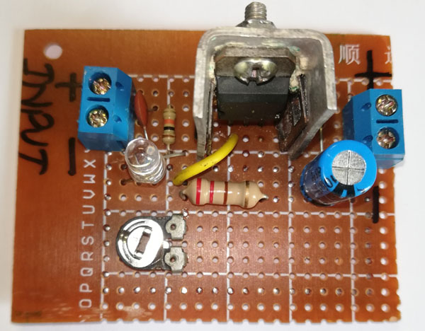
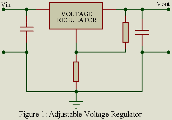
The basic circuit of Adjustable Output Voltage Regulator is essentially the same as for fixed output voltage regulators, but there is provision for an external resistive divider or potentiometer to adjust the output voltage. Positive or negative polarity output voltage can be obtained by the same type of connections described in Fixed Output Voltage Regulator.
Most of the adjustable type voltage regulators also contain one or more protective features such as over-voltage and over-temperature shutdown. Manufacturers data contain specific resistance values and/or potentiometer connections to provide the desired output voltage for a specified input voltage.
Key parameters of Adjustable Output Voltage Regulator
Essentially the same as for the fixed output voltage regulator, except for the following:
Output Voltage: The regulated output voltage maintained over the range of voltage from 1.2V to 37 V in both polarities i.e. positive as well as negative DC voltage.
Input voltage: Input voltage must greater then output voltage by VREF. Where VREF = 1.25V. Therefore we can say that input voltage = 1.25+ output voltage.
Safe operation area (SOA): Combination of maximum output current and the voltage difference between input and output voltage. Manufacturers data contain coordinates and a curve that must be used by the designer to locate the input and output voltage range, and output current, within the safe operating area.
Load Regulation: It indicates the change in the output voltage when the load current changes from no load to full load condition. It is denoted by LR.
Load regulation (LR) = VNL – VFL
Where, VNL = output voltage at no load
VFL = output voltage at full load
Percentage (%) regulation =
A typical value for variable voltage regulator is 0.1% over the specified range of load current.
Line Regulation: It indicates the change in load voltage for a specified range of input voltage. It is denoted by SR.
Line regulation (SR) = VLH – VLL
Where,
VLH = Load voltage with high line voltage
VLL = Load voltage with low line voltage
Percentage (%) Regulation =
Where, VNOM is the normal load voltage under the typical condition. Line regulation is also sometimes called as source regulation. Often stated in millivolts for 1-volt changes, a typical line regulation is 0.1% per volt for variable voltage regulator.
Applications of Adjustable Output Voltage Regulator
In many types of analog equipment, the regulated power supply output voltage must be carefully adjusted for optimum circuit performance. Photo tubes and transistors are typical of devices for which adjustable, regulated, power supplies are required.
What is the advantage of adjustable voltage regulators over fixed voltage regulators?
The adjustable voltage regulators offer variety of performance and reliability advantages over fixed voltage regulators i.e. improved system performance by having line and load regulation of a factor of 10 or better. Also, it improves the system reliability and performance.
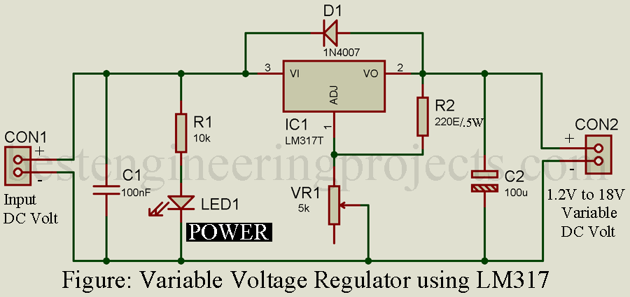
Representative Part Number: National Semiconductor LM317 (positive adjustable voltage regulator) National Semiconductor LM337 (negative voltage regulator circuit).

Previously, we had already posted the Adjustable Bipolar Voltage Regulator Circuit using LM317 and LM337. This circuit provide variable output voltage of 1.2V to 20V in both polarities i.e. to
.
Solved Numerical:
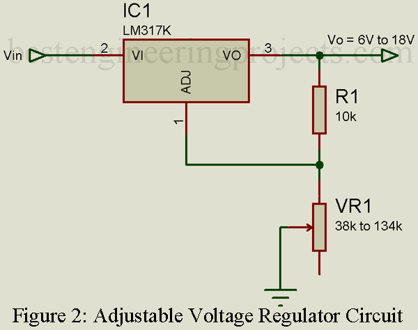
Design a dc voltage regulator for VOUT = 6V to 18V.
Ans: here, we have to design a voltage regulator with adjustable output requirement. Therefore, we shall use LM317 adjustable IC voltage regulator.
For the circuit,
Typically, and
Since, the value of IADJ is negligible small we shall ignore its value in our design and calculation.
Rearranging the equation,
When VO = 6V,
Therefore,
When VO = 18V,
Therefore,
Taking
For ,
For ,
.
Thus, if we take , then the output voltage can be obtained in the range VO = 6V to 18V by taking a variable resistor R2 having resistance in the range
to
.
Making video of Adjustable output voltage regulator circuit.


