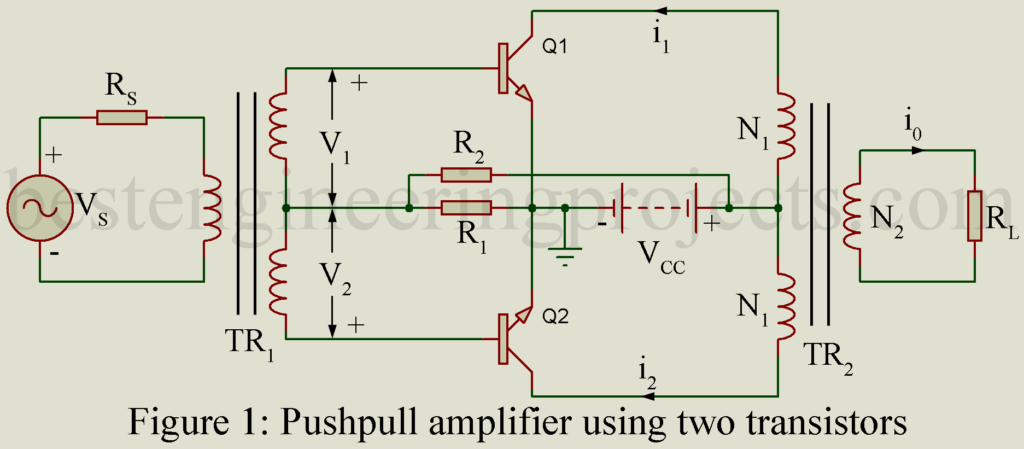
In a power amplifier using only one transistor, referred to as single ended amplifier, in spite of all care in design and operation, appreciable distortion results due to non-linearity of transfer characteristics. Such a distortion may be greatly reduced by using pushpull operation employing two transistors in a single stage as shown in figure 1. In the pushpull amplifier, the input signal is applied to the input of the two transistors through a centre tapped transformer TR1.
Then the voltages V1 and V2 across the two halves of the center tapped secondary are equal in magnitude but opposite in phase. Voltage V1 forms the input to transistor Q1 i.e. gets applied between its base and ground. Similarly, voltage V2 forms the input to transistor Q2.
Let the voltage V1 be,
……(1)
Then voltage V2 forming the input to the transistor Q2 is equal and opposite to Q1 and is, therefore, given by,
…….(2)
Then the collector current i1 of transistor Q1 is given by,
…….(3)
The collector current i2 of transistor Q2 may be obtained from equation (3) by replacing by
in each term. Thus, we get,
…..(4)
……..(5)
Collector currents i1 and i2 flow through the primary of the output transformer TR2 in opposite directions. Hence the resulting output current i0 in the secondary of transformer TR2 is proportional to the difference the collector i1 and i2. Thus, we get,
…….(6)
……….(7)
From equation (7) we conclude that the due to pushpull operation, all even harmonics i.e. terms in frequencies etc. get eliminated in the output. Only the odd harmonic distortion terms i.e. terms in frequencies
etc remain in the out[ut. But in general, the magnitude of harmonic terms go on decreasing as the order of harmonic increases.
Hence in the pushpull amplifier output, the third harmonic distortion term alone is of significance, while the higher order odd terms namely etc. are insignificant. This elimination of even order harmonic terms forms an important merit of pushpull amplifier. Of course, this complete elimination of even harmonic distortion terms is obtained in practice only when (i) the two transistor Q1 and Q2 have identical characteristics and (ii) the center tap on the secondary of input transformer TR1 is true electrical center of the secondary winding.
Merits of Pushpull Operation
- Even harmonic distortion terms generated within the amplifier get eliminated in the output.
- Absence of even harmonics permits us to draw more output power per transistor for a given permitted distortion. Alternatively, pushpull operation provides amplification with less distortion for a given power output per transistor.
- DC components of collector current of the two transistors produce opposing magnetic flux through the core of the output transformer. This avoids the possibility of dc saturation of the core and hence eliminates the consequent nonlinear distortion resulting from the curvature of the transformer magnetization curve.
- Effect of the ripple voltages which may be present in the power supply due to insufficient filtering get balanced out in the output. This cancellation is caused due to the current produced by these ripple voltages following in the opposite directions in the primary of the output transformer TR2.
However, hum component is not eliminated by the pushpull circuit.
