Power supply has a considerable role in electronic communications equipment. The power supply furnishes the voltage and current requirements for electronics circuit operation. Special high-voltage power supplies used in microwave systems and laser systems enable large power handling tubes and semiconductor circuits to operate. In this section, we are going to look at popular types of power supply circuits and some faults that can occur in them.
In this section, we’ll also learn to troubleshoot a traveling wave tube amplifier. Improper operating of a TWT can nearly always be traced to a power supply. There are a few rules you must know to do the job. Violation of the rule will result in the loss of the tube. Please be aware that extreme caution must be observed when dealing with power supplies. The ac line voltage and any high-voltage outputs can be lethal. After completing this section, you should be able to.
- Identify a switching power supply
- Identify a linear power supply
- Name the cause of high ac ripple on a power supply output
- Name a cause for a blown fuse in the primary winding of a power supply transformer
- Identify possible failure modes in a TWT amplifier
Problem and Troubleshooting of Power Supply
Two popular supplies are found in electronic equipment today. These are the linear power supply and the switching power supply. Many variations exist of both kinds of supplies. The linear power supply usually has a power transformer that is large and heavy. The linear supply furnishes a constant output voltage to a load. Excessive power is usually wasted in this kind of power supply in the form of heat. Because of this wasted power, efficiency is low. A typical linear power supply is illustrated in figure 1.
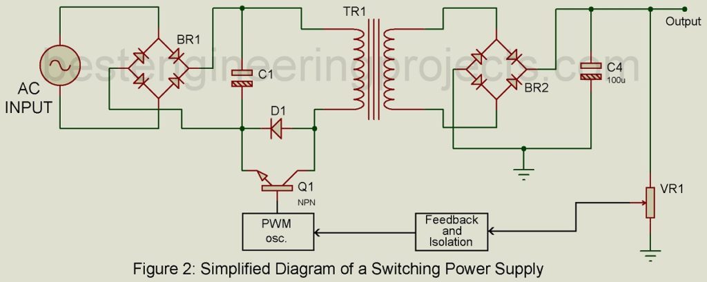
The switching power supply is light and does not use a large bulky power transformer. Instead, a smaller transformer is used. A diagram of the switching power supply is shown in figure 2. The input ac voltage is rectified, filtered, and applied to the transformer TR1. The power transistor, Q1, in the negative supply line is switched on and off at high-frequency rate, 20 to 40 kHz. The load requirement will determine the output of the supply. If the load requirement goes up, the supply furnishes more power. If the load goes down, less power is supplied. Power is not waisted as in linear power supply.
High-efficiency rates are achieved in the switching power supply by feeding a portion of the output voltage back to control an oscillator. The oscillator is part of a width-modulation circuit. A pulse width modulation circuit. A pulse-width-modulated signal is supplied to the base of the power transistor Q1, which regulates the transistor’s duty cycle. An increase of Q1’s duty cycle will increase the output voltage to maintain regulation. A decrease in the duty cycle will decrease the output voltage.
Troubleshooting the Linear Supply:
The linear power supply not only provides operating voltage and current to the electronic circuits connected to it but must also provide decoupling for them as well. The well-designed power supply will apply as a low impedance to the decoupled frequencies. If the power supply does not provide decoupling, problems like low-frequency oscillation and distortion can occur in the audio circuits. Hum in the output is caused by a bad filter capacitor. Capacitor C1 in figure 1 is the input filter capacitor. This capacitor reduces ac ripple in the dc output of the power supply. For a high-ripple problem, replace C1. The service manual normally specifies the maximum allowable ripple in the dc output voltages. Voltage is regulated by IC1 in figure 1. If IC1 fails to regulate, a higher than normal voltage will appear at the output. Many power supplies have several regulator circuits operating. Check each specified output voltage against actual measurements to ensure the supply is operating correctly.
The diodes, D1 – D4, form a full-wave bridge circuit that rectifies the ac from the transformer’s secondary winding. If any of the diodes should be short, the fuse in the transformer’s primary winding will blow. If the power supply blows fuses, suspect a shorted diode. High-wattage resistors in the power supply circuits are subject to changes in the value that could change an output voltage. Power transistors are often used in the regulator circuits. These are usually mounted on heat sinks and may short out. A shorted power transistor will most certainly blow a fuse and may even burn up any resistor in series with it. When troubleshooting power supplies, look for blown fuses, burned resistors, corroded solder joints, and leaky filter capacitors.
Troubleshooting the Switching Power Supply
Switching power supplies are often more difficult to troubleshoot because of the feedback circuit used to regulate the power supply’s output. The feedback circuit is a closed-loop system. Breaking the loop is the most effective way to isolate a feedback problem. The closed-loop in figure 2 consists of VR1, the feedback and isolation block, the PWM oscillator, and Q1.
Any one of these can cause the switching power supply to shut down or operate poorly. For example, if all the outputs are low or all output is high, suspect a feedback loop problem. If the protection diode, D1, continually blows, the feedback loop is the likely candidate. If only one or two output voltages are low, check the filter capacitor associated with those outputs.
The switching power supply can EMI radiation (electromagnetic interference) into the nearby communications gear on the circuits it is supplying, if not properly filtered. EMI filters protect other circuits from this interference bypassing the interference to the ground. Bad filters will let the power supply generate noise. Use the oscilloscope to monitor the outputs for noise, ripple, and unusual interference. The switching power supply must not be operated without a load connected to it or damage will most likely occur. As stressed in earlier troubleshooting sections, follow a logical troubleshooting plan when tracking down a proper supply fault.

