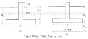
Terzaghi has developed the bearing capacity equation on the assumption that water table is at great depths. If water table is present close to the foundation, some modification is necessary. This is done as per the followings. Case 1 Water table above footing base The weight of soil below water table is reduced due to buoyancy. The influence of water table on bearing capacity is incorporated in the general bearing capacity equation with the help of Fig.1. Let, Zw1 = Depth of water table below ground level a = Height…
Read MoreFactor Affecting bearing capacity | Granular Soils | Cohesive Soils
What are the factor affecting bearing capacity? The bearing capacity of soil is influenced by various factors. The bearing capacity for cohesive and cohesionless soil is different. The physical features of foundation such as type of foundation, size of foundation, depth of foundation and shape of foundation significantly affect the bearing capacity. The amount of total and differential settlement is one of the main controlling factors for the bearing capacity of the soil. The relative density in the case of granular soil and consistency in the case of cohesive soil…
Read MoreTerzaghi’s Theory on Bearing Capacity Analysis
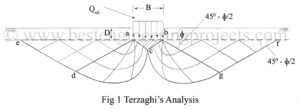
Terzaghi in 1943 gave a general bearing capacity theory for a strip foundation, called “Terzaghi’s Theory on Bearing Capacity Analysis“. For the first time, he developed his theory by incorporating the weight of the failure wedge in the analysis. Terzagi considered a continuous footing of width B placed at a depth of D below the ground surface as shown in fig.1. In the derivation of the equation, the following assumptions were made. The soil is homogeneous, isotropic and Columb’s law of shear strength is valid. The footing is continuous and…
Read MoreDevelopment of equation of Bearing Capacity by Prandtl
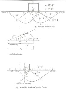
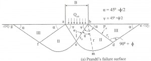
How to Development of equation of Bearing Capacity by Prandtl? equation of Bearing Capacity by Prandtl: As failure surfaces are symmetrical only forces acting on the right side of the wedges are considered. According to Prandtl, the bearing pressure Qult acting at the base ab of the footing is transmitted through the soil wedge abc on to the face bc, according to the Pascal’s law, pressure is undiminished and same in all direction. The state of stress within the wedge on the line bc may be explained with respect to…
Read MorePrandtl and Bell Theory on Bearing Capacity Analysis
Prandtl and Bell Theory on Bearing Capacity Analysis: Prandtl 1920 developed an equation based on his study of penetration of long hard metal puncher into softer materials for computing the ultimate bearing capacity. Assumptions made by Prandtl and Bell Theory on Bearing Capacity Analysis The material is softer, homogeneous and isotropic. The material is weightless and possesses only friction and cohesion. The problem is two dimensional The base of the puncher is smooth. The material behaves as a rigid body. The volume change will be Zero. The resulting deformation will…
Read MorePiled Foundation | Types of Pile
Piled Foundation: A pile is a slender structural member having very small area of cross-section relative to its length. It is a deep foundation where depth is greater than the width. It is used when shallow foundations cannot support the structure. Design Criteria of Piled Foundation A pile foundation must fulfill the following requirements: The material itself must not be over-stressed There must be an adequate factor of safety against a shear failure The settlements must be within the tolerable limits It should not over stress the underlying soft strata.…
Read MoreBearing Capacity Analysis | Pauker – Rankine Method
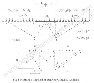
Bearing Capacity Analysis | Pauker – Rankine Method The methods suggested by Pauker Rankine Method are based on theory of classical earth pressure. This was postulated by Pauker a military engineer in 1850 and then modified by Bell in 1915. Pauker’s theory is only applicable to sands. Bell extended this theory for cohesive soils. Both the theories have not taken into account the width of the foundation. Since the equation has been developed based on Rankine’s earth pressure theory, the theory is called as Rankine’s theory for the determination of…
Read MoreTypes of Shear Failure
What are the types of shear failure? According to Vesic (1973) there are three types of shear failures. They are: General Shear failure Local Shear failure Punching Shear failure These failures are illustrated in Fig 1, 2 and 3. General Shear Failure – This type of failure occurs in stiff clay or dense sand. In this type of failure, failure takes place at a very small strain. The load settlement curve shows a well-defined peak as shown in Fig.1. At failure entire soil mass within the failure wedge participates and well…
Read MoreBearing Capacity Theories
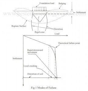
Bearing Capacity Theories: When a footing is placed on a soil, the soil deforms and foundation settles as shown in the figure 1. Before failure takes place, the soil below the foundation undergoes into various stages. At first the soil gets distorted. Local cracking follows this after which a rigid cone of the soil is formed directly below the footing. Lastly rupture surfaces are developed and failure of the soil occurs along these rupture surfaces. The stages of failure of bearing capacity theories foundation soil are briefly described below. Distortion…
Read MoreStability Analysis for Cantilever Wall
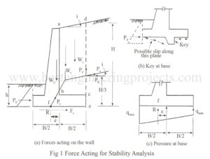
Derivation of Stability Analysis for Cantilever Wall Consider a cantilever wall carrying a sloping backfill as shown in the Fig.1. The various forces acting on the wall are: Pa = Active earth pressure acting at a height H/3 from the base on section ed. Ph = Pa cosi Pv = Pa sini Ws = Weight of soil abcd Wc = weight of wall including base Wt = the resultant of Ws and Wc Pt = the resultant of Wt and Pa meeting at f at base of Wall Pp =…
Read More