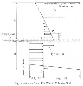
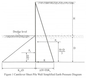
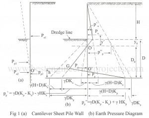
A cantilever sheet pile is shown in Fig.1 below. The Fig,1 also shows the pressure distribution. When the wall rotates about the point O’, the various pressures acting on the wall are: Pa1 = Active earth pressure on the back of the wall above the point O’ Pa2 = Active earth pressure in front of the wall below the point O’ Pp1 = Passive earth pressure in front of the wall above the point O’ up to dredge line Pp2 = Active earth pressure on the back of the wall…
Read MoreStructures of Cantilever Sheet Pile Wall
Cantilever sheet piles are used where the height of the soil or water to be retained is smaller than 4.5 m. The various forces acting on a cantilever sheet pile wall are the active earth pressure on the back of the wall and the passive earth pressure on the front of the wall. The active pressure tends the wall to move away from the backfill while the passive earth pressure resists the wall movement. General Principle of Design of Structures of Cantilever Sheet Pile Wall Figure 1 shown below illustrates…
Read MoreSheet Pile Walls | Types of Sheet Pile Walls
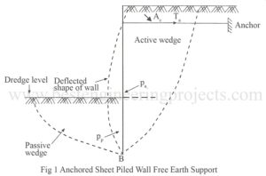
A sheet pile wall consists of a series of sheet piles driven side by side into the ground. This results in a continuous vertical wall for the purpose of retaining an earth bank. A sheet pile wall is a flexible wall having negligible weight and weight has no control over the wall stability. The stability is entirely due to the passive resistance developed between the wall and the soil. Sheet piles wall are generally used for water front structures, temporary construction, lightweight construction, coffer dams, riverbank protection and retaining the…
Read MoreHearing Aid Circuit
The hearing aid circuit available in the market are fully transistorized and generally use a single pen cell. The hearing aid circuit uses an IC LM358 (IC1) for the same purpose which give better sensitive and performance. You can also check DIY Hearing Aid Circuit using 555. Circuit Description of Hearing Aid Circuit Operational amplifiers are used here in their simplest from non-inverting AC amplifier with a gain of 100. Op-amp A1 forms the first-stage amplifier. Second-stage amplification is given through op-amp A2. Hence the total gain is 10,000. Resistors…
Read MoreGuitar Amplifier | Convert Hawain Guitar to an Electric Guitar
Whereas an electric guitar with 60W PMPO (Peak Music Power Output) costs around $8, here is a cost effective solution to convert a Hawain guitar to an electric guitar. The circuit Guitar Amplifier | Convert Hawain Guitar to an Electric Guitar can also be used as an ampli-speaker with a tape recorder or a radio receiver. Circuit Description of Guitar Amplifier | Convert Hawain Guitar to an Electric Guitar The unit can easily be assembled on a standard TBA810 ampli-speaker PCB available in the market. It is also be housed in…
Read MoreAudio Running Lights Circuit
Here is a project for audio running lights circuit which uses filament bulbs instead of LEDs. The circuit employs seven channel darlington array IC ULN2004 and seven reversed biased zener diodes having different breakdown voltages. At low audio level, zener diodes having low breakdown voltages will conduct and corresponding lamps will light up. When output level increases, the other diodes will also conduct. As a result, you can see a very fine display of ‘moving’ light bulbs from top to bottom or from left to right, as per their arrangement.…
Read More100 Rung Exclusive Counter
Digital counters are frequently needed in all kinds of counting circuits, test gear, sequential displays, timers, etc for up to ten outputs (exclusive and independent), or 16 at the most. But the problem arises when it comes to using more than these many outputs. In such a case, the 4017-based CMOS counter can be put to use as a 100-stage counter. The circuit configuration uses a dozen 4017 counter ICs. IC12 sends clock pulses to IC11 at one-tenth of its input frequency, which in turn allows Qa through Qj to…
Read MoreElectronics Fuse Circuit | Electronic Circuit Breaker
Fuse protection for electronics circuits seems to be an outmoded idea, for there are circuits (in computers etc) that consume high currents initially at a lower stable value. In case high-rated fuses are employed in such equipment to accommodate the initial surge current, it defeats the very purpose of protection. Slow-blow fuses often turn out to be too slow while quick-action fuses may blow out at the mere hint of a surge. An electronics fuse circuit of the kind described here provides an ideal solution in such cases. An electronic…
Read MoreDigital Clock Circuit with Seconds and Alarm Time Display
Most of the digital clock available on the website is only capable to display hour and minute only. Now, here is a project called Digital Clock Circuit with Second and Alarm Time Display which shows not only Âhour, minute, and second but also alarm time. Best Engineering Projects (BEP) verify the project Digital Clock with Second and Alarm time display with the help of ten 7-segment displays and clock chip mm5387ANN. Circuit Description of Digital Clock Circuit with Seconds and Alarm Timer Display The entire circuit of the Digital Clock…
Read MoreUltrasonic Lamp Brightness Controller Circuit
Wireless control of devices using infrared is not new to electronics hobbyists. Now, here is wireless control of the device using ultrasonic sound waves tested in BEP Lab. The project ultrasonic Lamp brightness controller circuit uses ultrasonic sound waves (above 20 kHz) for remote control of lamp brightness. Circuit Description of Ultrasonic Lamp Brightness Controller Circuit As with all wireless control systems, the Ultrasonic lamp-brightness controller comprises a transmitter and receiver circuit. Transmitter Circuit |Â Ultrasonic Lamp Brightness Controller Circuit The transmitter circuit generates an ultrasonic sound wave of about 40-50…
Read More