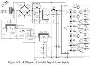
Various types of power supply circuits like fixed regulated, variable power supply, and stabilized power supply circuits are already published on bestengineeringproject.com. Most of us hear about the universal power supply, it is a power supply unit that provides almost all standard power supply. How’s that if we combine a universal power supply and a digital control technology. Here, the innovative group of Dreamlover Technology designed and verified a universal power supply circuit with the facility of digital control. The unit universal digital power supply provides a variable, fluctuation-free and…
Read MoreStabilized Power Supply With Short-Circuit Indication
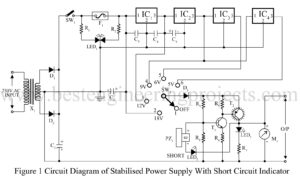
Various power supply-based project is already posted on bestengineeringprojects.com. Now, here is a stabilized power supply circuit with the facility of short-circuit indication. As we know that stabilized power supply is used for testing various electronics circuits and is very important for electronics geeks or hobbyists. The circuit presented here is of a 5-stage stabilized power supply unit and it provides well-regulated output, which is essential for most electronics circuits for proper results. Another advantage of the circuit stabilized power supply with short-circuit indication has it provides an audio-visual indication…
Read MoreMains line frequency meter circuits
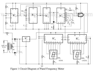
Generally, the standard line frequency in some countries is 50HZ or in some countries 60HZ, which may vary from time to time. Due to this varying nature of frequency, sensitive equipment may start malfunctioning, and the requirement result we may not get. New here is a simple mains line frequency meter circuit designed and verified at BEP (Best engineering project) lab used to measure the frequency of AC mains. Circuit description mains line frequency meter circuit The circuit of the mains line frequency meter is built around timer IC2 (NE555),…
Read MoreLight Controlled Digital Fan Regulator Circuit
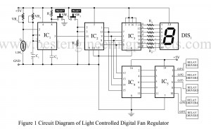
Mans are born of habit, and we all want comfortable. At night while sleeping we often switch of the light. But sometime we used to increase or decrease the speed of fan. And it is very difficult to trace the switch board in a dark room at night and to wake-up from bed is also irrigative. By keeping this problem in mind the group of electronics geek at Dreamlover technology designed and verified a electronics project called light controlled digital fan regulator circuit. You can also check this awesome project IR…
Read MoreFrequency Generator and Divider circuit
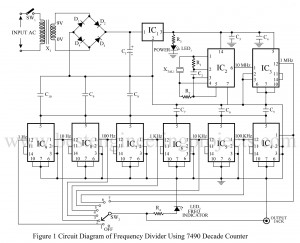
What are Frequency Generator and Divider Circuit? A frequency generator is a circuit that generates a frequency and a divider circuit divides the generated frequency with various factors to get different frequency values. Various assembled frequency generators and divider circuits are available in the market but they are quite expensive to buy. The group of electronics geeks at dream lover technology designs a low-cost square wave signal generator and divider circuit. The frequency of 1 Hz, 10 Hz, 100 Hz, 1 kHz, 100 kHz, and 1 MHz are obtained at…
Read MoreAll in One Tester Circuit
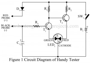
All in one multi-tester is quite expensive which may not affordable for every electronics beginner. Now, here is s cheap all-in-one tester circuit that can be used to test the condition of almost all the electronics components from the basic resistors to advance ICs. The circuit all in one tester is used to detect polarity, continuity, logic state, and also activity of multivibrator. Description of All in One Tester Circuit The circuit of the all-in-one tester is so simple that it can also understand by beginners. The circuit of all…
Read MoreMultiband CW Transmitter
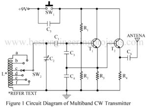
A frequency oscillator is used to generate frequency oscillation, and a radio frequency oscillator is used to generate high-frequency which is known as a carrier wave. The circuit multiband CW transmitter is a continuous wave (CW) transmitter for transmitting morse code signal in a shortwave band. The circuit posted here is a variable frequency oscillator (VFO) whose frequency can be varied from 5.2 MHz to 15 MHz. The transmitted signal from this circuit can be received in a short wave band by any radio receiver. Circuit Description of Multiband CW…
Read MoreDC Motor Control Circuit
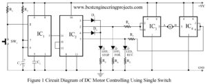
The various motor control circuit is already available on the internet and this is also not a new idea for the electronics hobbyist. The circuit of the DC Motor Control Circuit, published here is different from another circuit available for motor control because it let you run a DC motor in a clockwise or anti-clockwise direction and stop it using a single switch. DC motor control circuit has also another advantage i.e. for proper operation of the motor this circuit provides a constant voltage. Here we use three LEDs LED1…
Read MoreDome Lamp Dimmer Circuit
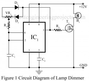
As we have already published various types of lamp dimmer like Light Dimmer Circuit using Capacitor and Touch Dimmer Circuit using triac etc. Now here is a lamp dimmer for the dome lamp in the car, which gives a fairly linear control over the lamp brightness from low to high intensity. The main advantage of the project dome lamp dimmer circuit is it consumes little power because it is a pulse-width modulated chopper circuit. You can also control the intensity of a halogen bulb or control the speed of a…
Read MoreVoltage window comparator Circuit follows reference voltage
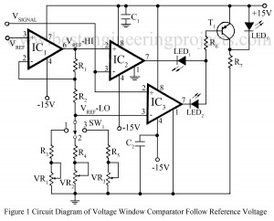
The use of window comparators are essential in the test circuits which perform the ‘GO-NO-GO’ tests for the various electronic components likes zener diodes, transistors, relays etc. The upper and lower threshold voltages are set for the window comparators depending upon the values and tolerances of the components to be tested. Here is a window comparator circuit in which the window width is automatically adjusted to be a fixed percentage of the input reference voltage Vref proportional to the nominal value of the component under test and produces an upper…
Read More