Mans are born of habit, and we all want comfortable. At night while sleeping we often switch of the light. But sometime we used to increase or decrease the speed of fan. And it is very difficult to trace the switch board in a dark room at night and to wake-up from bed is also irrigative. By keeping this problem in mind the group of electronics geek at Dreamlover technology designed and verified a electronics project called light controlled digital fan regulator circuit. You can also check this awesome project IR Remote Controller Fan Regulator using AT89C2051.
By using this circuit one can control the fan speed with a torch light remotely from the bed. The speed of fan can be varied by number of times focus on the LDR (light- dependent resistance) of the circuit. LDR is a semiconductor which changes their resistance according to the intensity of light.
Description of light controlled digital fan regulator circuit
The circuit of light controlled digital fan regulator circuit is build around times IC, decode counter (7490), BCD to 7-segment driver(7447), BCD –to decimal decoder, hex inverter, common-anode 7 segment display, LDR and few other components.
Timer IC (IC1) is configuring in monostable mode (timer) and its time period is adjusted to 1.3 seconds. The fan regulator is triggered when torch light fall on LDR1. In every focus of torch light the resistance of LDR1 goes low which trigger IC1. The every monostable clock is counted by decode counter IC2, given to pin 14 or clock pin as shown in circuit diagram. The output of IC2 is given to IC3 and IC4 parallel.

IC3 is a 7 segment display driven where output is given to 7-segment display. Here 7-segment display is used to display the number of times you focus the torch light on LDR1. As shown in table1 in every even number the fan will be off, where with increase in odd number, the speed of fan also increases.
The output of IC4 (BCD to-decimal decoder) is given to hex inverter IC. The output from pin 2,4,6,9 and 11 is given to reply driver circuit through corresponding reply driver circuit. The even number output of IC4 is not used. Due to this the fan turns off in every even-number.
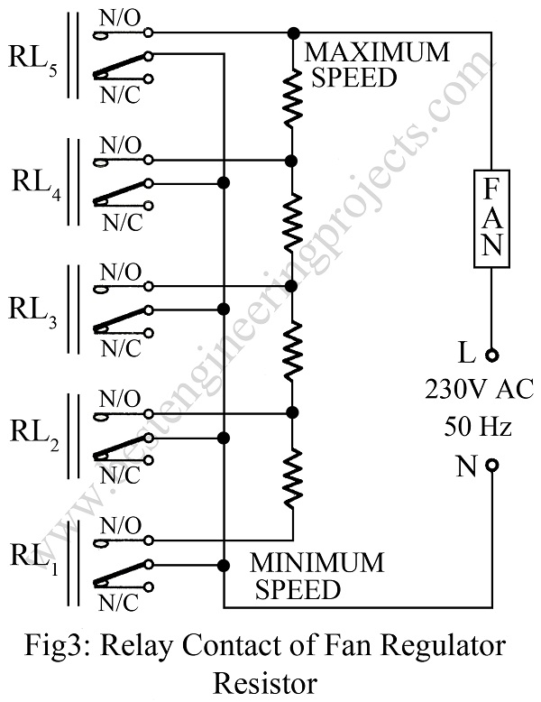
Switch SW1 and SW2 is used to reset IC1 and IC2 respectively. The relay circuit is build around a transistor as shown in fig 2. The output of hex inverter IC5 is connected to base of rely driver transistor through resistor 4.7 KΩ. Similar individual circuit is build for each relay. The normal opened (N/O) contact of rely RL1 through RL5 are connected to regulating resistor shown in fig 3.

For this circuit to work even in the presence of ambient light for example, during day time, LDR1 is made dark by covering it with an inked paper.
|
TABLE 1 |
|||
|
Fan Control with Torch Light Focused on the LDR |
|||
|
No. of focus on LDR |
Display DIS1 |
Energized relay on |
Fan Speed |
|
0 |
0 |
– |
OFF |
|
1 |
1 |
1 |
1 (min) |
|
2 |
2 |
– |
OFF |
|
3 |
3 |
2 |
2 |
|
4 |
4 |
– |
OFF |
|
5 |
5 |
3 |
3 |
|
6 |
6 |
– |
OFF |
|
7 |
7 |
4 |
4 (max) |
PARTS LIST OF LIGHT CONTROLLED DIGITAL FAN REGULATOR CIRCUIT
|
Resistor (all ¼-watt, ± 5% Carbon) |
|
R1, R2 = 1 KΩ R3 – R9 = 330 Ω R10 – R14 = 4.7 KΩ (relay driver circuit) VR1 = 10 KΩ VR2 = 100 KΩ |
|
Capacitors |
|
C1 = 22 µF, 10V (Electrolytic Capacitor) C2 = 0.01 µF (Ceramic Disc) |
|
Semiconductors |
|
IC1 = NE555 (Timer IC) IC2 = 7490 (Decade and Binary Counter) IC3 = 7447 (BCD to 7 Segment Decoder) IC4 = 7442 (BCD to Decimal Decoder) IC5 = 74LS04 (HEX Inverter IC) T1 – T5 = SL100 (for relay driver circuit) D1 – D5 = 1N4007 (for relay driver circuit) |
|
Miscellaneous |
|
DIS1 = LTS542 (Common-anode seven segment display) SW1, SW2 = Push-to-on switch RL1 – RL5 = 6V, 100Ω 1C/O relay LDR1 |
Hi Author of this project,
I want to know resistor values used in figure.3 of this project.
Kindly support for same asap as other two PCBs on general purpose PCB i already made.
Thanks in advance.
Your Sincerely,
Nainesh.
the connection shown in the figure is of normal fan regulator i.e. you can connect it with rotatory resistor of fan regulator
I don’t know what’s the value of rotary switch resistor can I get exact values of those 4 resistors ?
Thanks.for support.
Hi author,
Can I have resistor value of rotary switch you mentioned in above project ?
Nainesh.
please read the complete article before you ask any question.
Any way, resistors connected in rotary switch is just the fan regulator’s resistor.
simply bur a 4 or 5 speed fan regulator open up it ad you will see a rotary switch having 5 or 6 number of wire now simply connect that wire as resistor connection show in figure 3.
Hi Author of this project
Why this is not implement in each & every house yet …
what are the disadvantages?