All in one multi-tester is quite expensive which may not affordable for every electronics beginner. Now, here is s cheap all-in-one tester circuit that can be used to test the condition of almost all the electronics components from the basic resistors to advance ICs. The circuit all in one tester is used to detect polarity, continuity, logic state, and also activity of multivibrator.
Description of All in One Tester Circuit
The circuit of the all-in-one tester is so simple that it can also understand by beginners. The circuit of all in one tester contains two transistors and very few other passive components. Transistor T1 and T2 are used here as a switch, driving the one half of bicolor LED each in order to give the result of the test.
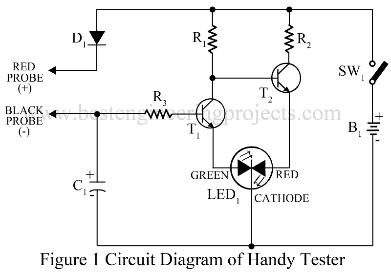
Initially, the circuit is in off mode, when switch SW1 is pressed, transistor T1 stops conducting due to a lack of forwarding bias. At the same time transistor, T2 takes base bias voltage from the battery through resistor R1 and conducts. This allows the red half of bicolor LED1 to illuminate.
Transistor T1 conducts when the positive voltage through resistor R3 is given to the base of transistor T1 and lights up the green half of LED1. In the conduction of transistor T1 transistor, T2 turns off and vice-versa.
Thus from the description, we know that the functioning of the circuit thus depends on the signal obtained at the base of transistor T1. The table below gives the testing procedure for various components with the expected indication or result.
Bi-Color LED Status for Various Tests |
||||
|
Component/test |
Test Procedure |
LED1 Status |
Result |
Note |
|
Continuity |
Red and black probes to the test points |
Green ‘on’ |
Continuity |
|
|
Red ‘on’ |
No continuity |
|||
|
Polarity |
Red probe to the positive of the circuit and black probe to the test point |
Green ‘on’ |
Positive |
The circuit should be ‘on’ |
|
Red ‘on’ |
Negative or no power |
|||
|
Logic |
Red probe to the circuit’s positive and black probe to the output |
Green ‘on’ |
High |
The circuit should be ‘on’ |
|
Red ‘on’ |
Low |
|||
|
IC |
Red probe to the circuit’s positive and black probe to the output |
Green ‘on’ |
High |
The circuit should be ‘on’ |
|
Red ‘on’ |
Low |
|||
|
Multivibrator IC 555 |
Red probe to the circuit’s positive and black probe to the output |
Color changes from red to yellow to green clinically |
IC oscillating |
The circuit should be ‘on’ |
|
Red ‘on’ |
No oscillation |
|||
|
Electrolytic Capacitor |
Red probe to the positive and black to the negative lead |
Green gradually turns red |
Capacitor good |
The capacitor should be discharged |
|
Red ‘on’ |
Capacitor faulty |
|||
|
Diode (LED/Photodiode/IR diode) |
Red probe to the anode and black probe to the cathode |
Green ‘on’ |
Good |
1 kilo-ohm resistor should be connected to the anode of LEDs |
|
Red probe to the cathode and black probe to the anode |
Red ‘on’ |
Good |
||
|
In both conditions |
Color remains the same (either green or red) |
Open /short |
||
|
Resistor (1 ohm to 500 Kilo ohms) |
Red and black probes to the ends of the resistor |
Green ‘on’ |
Good |
|
|
Red ‘on’ |
Faulty |
|||
|
Transistor |
Red probe to the base of the transistor and the black probe first to the collector and then to the emitter |
Green ‘on’ and again green ‘on’ |
Transistor conducts |
The circuit should be ‘on’ |
|
Black probe to the base of the transistor and red probe first to the collector and then to the emitter |
Green ‘on’ and then red ‘on’ |
Transistor doesn’t conduct |
||
Check out other various testing circuits posted in bestengineeringprojects.com
- Speaker Polarity Test Circuit
- Servo Motor Tester Circuit Using 555 IC
- Zener Diode Tester Circuit
- Relay Tester Circuit
- 5 State Digital IC and Circuit Tester
PARTS LIST OF ALL IN ONE TESTER CIRCUIT
|
Resistor (all ¼-watt, ± 5% Carbon) |
|
R1 = 1.8 KΩ R2 = 1.5 KΩ R3 = 4.7 KΩ |
|
Capacitor |
|
C1 = 1 µF, 16V (Electrolytic Capacitor) |
|
Semiconductors |
|
T1, T2 = BC548 (General Purpose NPN Transistor) D1 = 1N4001 (General Purpose Rectifier Diode) LED1 = Bi-color LED |
|
Miscellaneous |
|
B1 = 9V battery SW1 = on/off switch |
In 741 op-amp circuit tester, All the OP-AMP IC’s can be check
If you can manage their pin then, you can check almost all op-amp IC
can you give me the specific components in the handy tester? Thanks