High wattage power transistor is matched complementary pair are now readily available. Using such transistor, an economical high power amplifier using a minimum of components and giving a good performance can easily by constructed by an audio enthusiast. Thus, here we had designed a 20W Audio Amplifier Using ECN149-ECP149 Pair Transistor. Circuit Description of 20W Audio Amplifier Using Ecn149-ECP149 Pair Transistor A discrete power amplifier circuit is shown in figure 1 employs the 30W silicon output transistor pair ECN149-ECOP49. This amplifier will deliver 20W into 8Ωwith a 450mV input signal. We…
Search Results for: audio amplifier
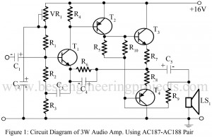
3watt Audio Amplifier Using AC187-AC188 Pair
The high wattage power transistor with matched complementary pair is now readily available. Using such a transistor, an economical high power amplifier using a minimum of components and giving a good performance can easily be constructed by an audio enthusiast. Here in this article, we are going to build a 3watt audio amplifier by using complementary pair of transistors. Circuit Diagram of 3watt Audio Amplifier Using AC187-AC188 Pair A discrete 3watt Audio power amplifier circuit is shown in figure 1 employs a complementary output stage featuring the AC 187-AC188 (T3…
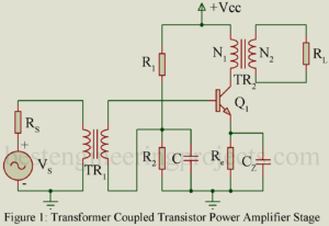
Transformer Coupled Audio Power Amplifier
Transformer Coupled Audio Power Amplifier: Untuned large signal amplifier (power amplifier) of class AB and B type invariably use transformer coupled stages while those of class A type also generally use transformer coupled stage. RC coupled stages are not used because the quiescent current flawing through the load resistor results in large wastage of dc power in it. This dc power dissipated in the load resistor does not contribute to the useful ac output power. Further flow of dc current through the output device is not desirable. Hence it is…
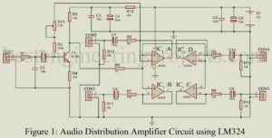
Audio Distribution Amplifier Circuit using LM324
Audio Distribution Amplifier is a circuit which transfer signal from one audio source to many output with a facility of appropriate amplification. The project published here is of Audio Distribution Amplifier Circuit using LM324 is shown in figure 1, which is basically a low cost, low noise amplifier designed using one of the most popular operational amplifier LM324. The circuit of audio distribution amplifier is combination of low noise input transistor amplifier and an op-amp in order to insure good characteristics. Circuit Description of Audio Distribution Amplifier using LM324 The circuit…
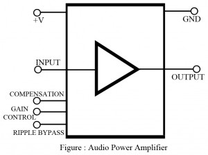
Audio Power Amplifier
Generally, audio power amplifier are low frequency (typically 40 Hz to 20,000 Hz) power amplifiers. Internally, they are designed as class B power amplifiers and offer reasonable power gain (5 to 10 watts typically, as well as low distortion figures. To handle the power dissipation required, most chips have several large, flat pins that are tied to ground and act as heat sinks. Chips such as these provide additional features as well, such as thermal shutdown protection, overvoltage protection, and frequency compensation. The output is designed to drive a low…
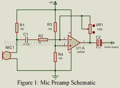
Mic Preamp Schematic: Elevate Your DIY Audio Projects
Are you on the hunt for a reliable mic preamp schematic to take your DIY audio projects to the next level? Look no further. In this article, we present a powerful yet straightforward mic preamplifier circuit that can transform whispers into a loud and clear conversation. Whether you’re a seasoned electronics enthusiast or a beginner, this schematic is perfect for boosting your DIY audio endeavors. Overview of the Mic Preamp Schematic The mic preamp schematic posted here uses the capabilities of a high-gain operational amplifier, the LM385. This versatile integrated…
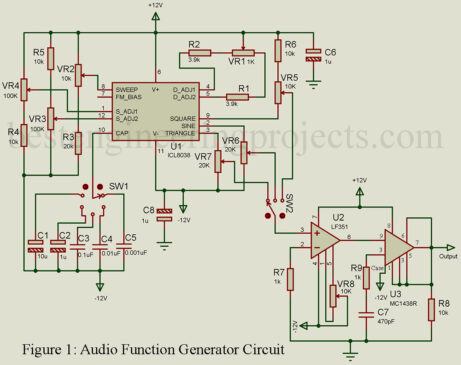
Exploring the ICL8038: Building an Audio Function Generator Circuit
Introduction: In the world of electronics, different types of waveforms are essential for testing various circuits. A sine wave signal is commonly used for assessing linear circuits such as amplifiers and filters. In contrast, a square wave input becomes crucial when testing digital circuits like flip-flops, counters, and registers. In this article, we’ll delve into constructing and operating an audio function generator utilizing the specialized integrated circuit, ICL8038. Notably, this audio function generator circuit offers not only sine and square waves but also triangle waves. Circuit Description and Operation of…
Linear Follower (Current) operational Amplifier
In the Article Linear Follower Amplifier we are going to discuss about current amplifier, its parameter, applications and comment. Current amplifiers are basically Class A Amplifier which usually have a voltage gain of 1 and effectively act as impedance transformers. Their main feature is their ability to develop a substantial output current. Sometimes they are called “linear followers,” similar to emitter follower transistor circuits. Current amplifiers are often used in series with an operational amplifier, inside the feedback loop, to provide additional output current. Key parameters of linear follower amplifier…
Class B, C and AB Amplifier IC
In this article we will see details like key parameters , applications and parts number of Class B, Class C and Class AB amplifier IC. Description of Class B Amplifier: In this type of amplifier, the quiescent (Q) point is set exactly at the cutoff of the IC curve, resulting in amplification of only one half-cycle of the input sinewave. Class B amplifiers are invariably connected back to back in push-pull circuits. In this arrangement one amplifier is operating during the positive cycle of the sinewave and is cut off…
Anti-logarithmic Amplifier IC
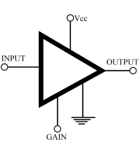
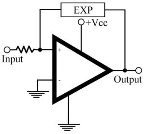
In the Anti-logarithmic Amplifier IC the output voltage is proportional to the log or to the exponential function (antilog) of the input signal. Most logarithmic amplifier ICs are available with an external strapping option that makes them operable in either the algorithmic or the exponential (antilog) mode, as indicator in figure 1. The antilog element consists of semiconductors stage in which the input voltage procedures a current that is an exponential function. To produce a logarithmic output, the antilog element is connected as part of the feedback circuit as shown…

