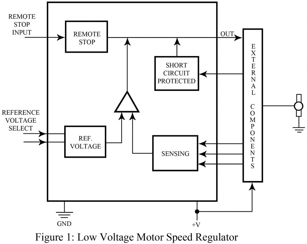
You might have noticed that the speed of DC motor is not stable throughout the project. It is because, as per the concentration or density of load on the DC motor, its rotational speed varies. For particular projects we require DC motors to operate with a constant speed. This is where this project; ‘Low voltage motor speed regulator’ is applicable.
However as depicted in the project title, it can be used only with the low voltage motors. This chip is used to regulate the speed of low voltage (5 to 20 V) DC motors. The chip ensures 1 to 3 % speed regulation when used in the project along with the external components like transistors, capacitors and resistors. To add more to this project, bonus features such as short circuit protection and remote pause control are included in the circuit which can be easily controlled via input pins.
The basic key parameters of Low Voltage Motor Speed Regulator are briefed in points below:
- Reference voltages: – By opening and grounding selective input pins, levels of reference voltages are programmed into the chip. On the way of doing so, the resultant voltage produced internally compensate for temperature variations of motor characteristics.
- Short circuit current limit: – The value of this current varies with the external resistor used to limit the short circuit condition. 1.4 A is the approximated value in general. In case the output current from the circuit exceeds the selected current limit, the additional current flow is interrupted. To resume the current flow, the supply voltage to the chip must be stopped.
Applications | Low Voltage Motor Speed Regulator
This project is designed with the sole purpose to regulate the speed parameter of low voltage DC motors.
Check out other motor driver and speed controller projects posted in bestengineeringprojects.com
- Motor Controller Circuit for Washing Machine
- BLDC Motor Driver Circuit
- AC Motor Speed Controller Circuit Using AT89C51
- DC Motor Control Circuit
- 3 Phase Induction Motor Starter
