The circuit and PCB Design of Low Power Audio Amplifier using LM386 is posted here which used to drive at most audio power of 1 Watt. LM386 is an low voltage, battery operated power amplifier designed for application where low voltage is main concern. The main advantage of using LM386 is it does not requires any ground reference voltage and it’s output is automatically biased to 1/2 of supply voltage.
Circuit Description of Low Power Audio Amplifier Using LM386
To derive at most audio power of 1 watt at the output terminal, a low power audio amplifier can be used together with any audio mixer circuit. Few of mixture circuit posted in bestengineeringprojects.com are listed here.
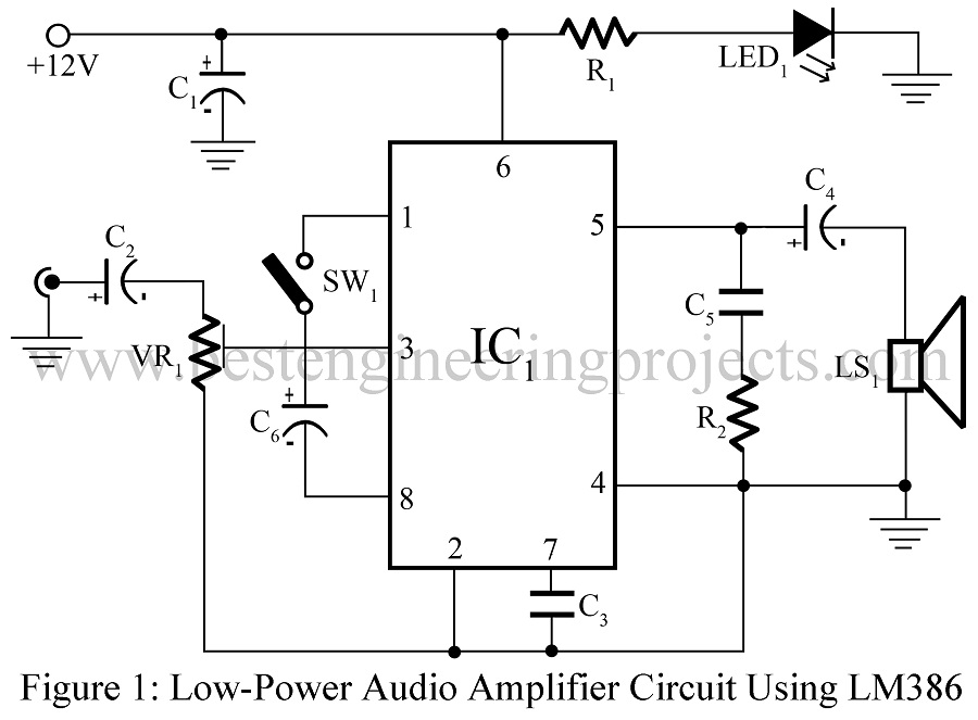
The circuit diagram of low power audio amplifier is shown in figure 1. It is a must to use IC LM386 (IC1) along with that amplifier. However, if required one can replace the low-power amplifier with high-power ones. The low power audio amplifier used in this project is fed with an external +12V DC supply through pin 6. IC1 intakes inputs from multiple audio sources and audio mixer via pin 3 after passing through potmeter; VR1 used as a volume control.

So as to keep low count on the external part, gain parameter of IC1 is initially set to 20. To extend its versatility and allow the user to obtain any gain value ranging from 20-200, a separate combination of resistor and capacitor is applied externally at pins 1 and 8. For maximum gain of 200 (46 dB), a single capacitor needs to be placed in between pins 1 and 8 using the switch SW1 as portrayed in figure.1.
Thus, produced output of IC1 is collected from the pin 5 and then passed towards the loudspeaker via electrolytic capacitor; C4. The pitch of frequency response in the audio system can be increased by replacing C4 with high value capacitor.
Construction of Low Power Audio Amplifier Using LM386
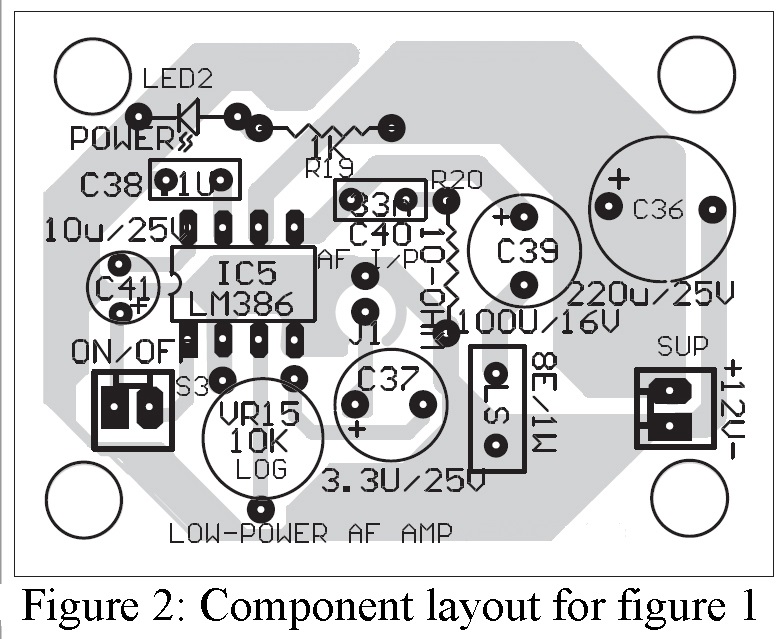
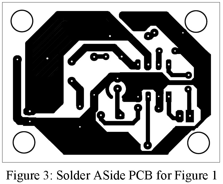
Once you understand the circuit diagram and operating principle of low power audio amplifier, it becomes very easy to implement in reality. For better working performance, you should use the components listed in parts list. Component side PCB layout and solder side PCB layout for figure 1 is shown in figure 2 and figure 3 respectively. Mounting of component on PCB should be done carefully and remember always use IC base. Because using of IC base makes easier to replacing of IC and it also protects IC from destroying while solder.
PARTS LIST OF LOW POWER AUDIO AMPLIFIER USING LM386
| Resistors (all ¼-watt, ± 5% Carbon) |
| R1 = 1 KΩ
R2 = 10 KΩ VR1 = 10 KΩ LOG. |
| Capacitors |
| C1 = 220 µF, 25V (Electrolytic Capacitor)
C2 = 3.3 µF, 25V (Electrolytic Capacitor) C3 = 0.1 µF (Ceramic Disc) C4 = 100 µF, 25V (Electrolytic Capacitor) C5 = 33 nF (Ceramic Disc) C6 = 10 µF, 25V (Electrolytic Capacitor) |
| Semiconductors |
| IC1 = LM386 (Low power audio amplifier IC)
LED1 = 5mm any color LED |
| Miscellaneous |
| LS1 = 8Ω/5W Loudspeaker
SW1 = ON/OFF Switch |

