The engineer like to communicate with their mates but radio wave is too easy to intercept using light with morse code is tricky. Here Laser Voice Transmitter Circuit uses a laser beam to transmit the voice.
Circuit Description of Laser Voice Transmitter Circuit:-
Most all communication systems comprised of two parts, the project laser voice transmitter also comprised of two parts i.e. the transmitter circuit and the receiver circuit.
The transmitter circuit:-
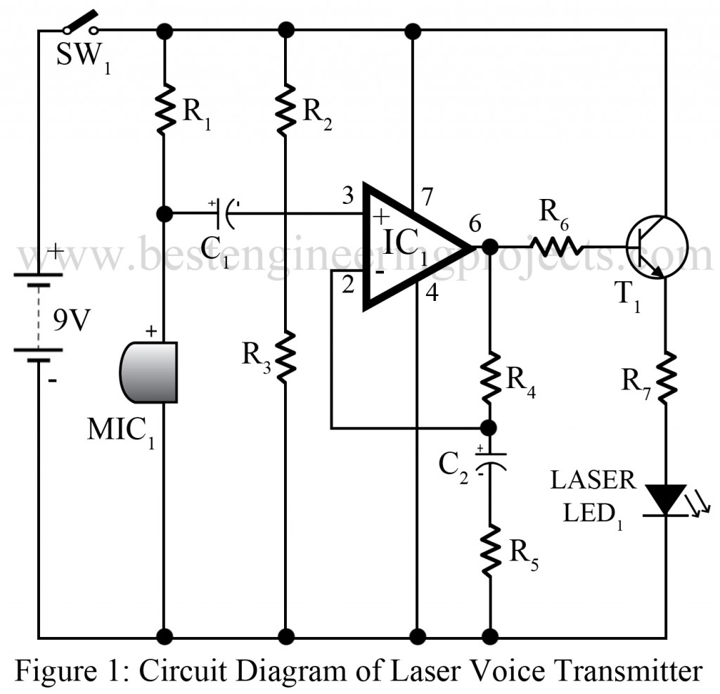
The transmitter circuit is built using a microphone, audio amplifier, laser diode, and a few passive components. A microphone is used here as a sound sensor that detects sound and changes it into an electrical signal. The signal coming from the microphone is very small to alter the power of laser light, so it needs further amplification. To amplify the signal we used here CMOS operational amplifier IC (7611).
The operational amplifier is used herein in non-inverting mode. The output electrical signal is connected to the positive amplifier input. This input is held halfway between GND (0V) and the supply voltage of 9V by resistor R2 and R3; however, it will fluctuate from this by the influence of the microphone.
A feedback network determines the gain of the circuit and is connected to the negative terminal (inverting terminal) of the operational amplifier. The formula for calculating the gain of the circuit is
Gain = (R4 + R5)/R5
And in this case it will (47+1)/1 = 40.
Therefore, the signal at output is multiplied by the input signal by a factor of 48.
This amplification provides sufficient amplitude or voltage to the signal and is given to the base of transistor T1 is used as a laser diode driver circuit where resistor R7 is worked as a current limiter.
Receiver Circuit:
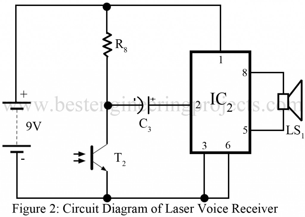
The receiver circuit is built around a signal audio amplifier IC (TDA 7205). A phototransistor detects light from the transmitter and allows it to conduct. The more light on the phototransistor, the more it conduct and vice versa. The output from the phototransistor is given to pin 3 of amplifier IC through capacitor C3. Where capacitor C3 is an AC coupling capacitor that blocks DC bias. The amplifier output is given to the loudspeaker directly.
The sensitivity of the circuit is determined by the resistor R8, the more value of the resistor increases the sensitivity, and the less value of the resistor decreases the sensitivity.
Check out more other interesting projects using Laser, posted on bestengineeringprojects.com
- Laser-Based Communication Link
- Speech Communication using Laser
- LASER Demonstration Program using C
- Mini Laser Turret
PARTS LIST
| Resistor (all ¼-watt, ± 5% Carbon) |
| R1 = 10 KΩ
R2 – R4 = 47 KΩ R5, R6 = 1 KΩ R7 = 47 Ω R8 = 10 KΩ, 0.5W metal film resistor |
| Capacitors |
| C1 – C3 = 1 µF (Electrolytic Capacitor) |
| Semiconductors |
| IC1 = 7611 (CMOS Operational Amplifier)
IC2 = TDA7205 1-Watt amplifier IC T1 = BC458 (NPN transistor) T2 = Phototransistor D1 = 5mW red laser diode module |
| Miscellaneous |
| SW1 = Toggle Switch
LS1 = Loud Speaker MIC1 = Condenser Microphone |
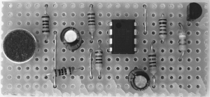
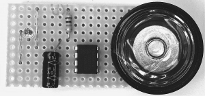
Complete Build Circuit of Laser Voice Transmitter
Fig: Transmitter Circuit
Fig: Receiver Circuit


sir what’s the uses of this laser voice transmitter
Th main use is, its tricky and is almost impossible to crack morse code unlike radio frequency. So it is quite confidential and fun too.
i want to med it
What is the value of R3 and c2?
Each Components value is given in parts list.
In parts list R2 -R4 = R2, R3 and R4 i.e. value of these resistor (R2, R3, R4) is same so for short we write R2 – R4. and same for capacitor.
Do you have any graphs showing the working of each unit