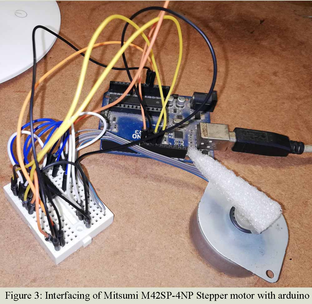
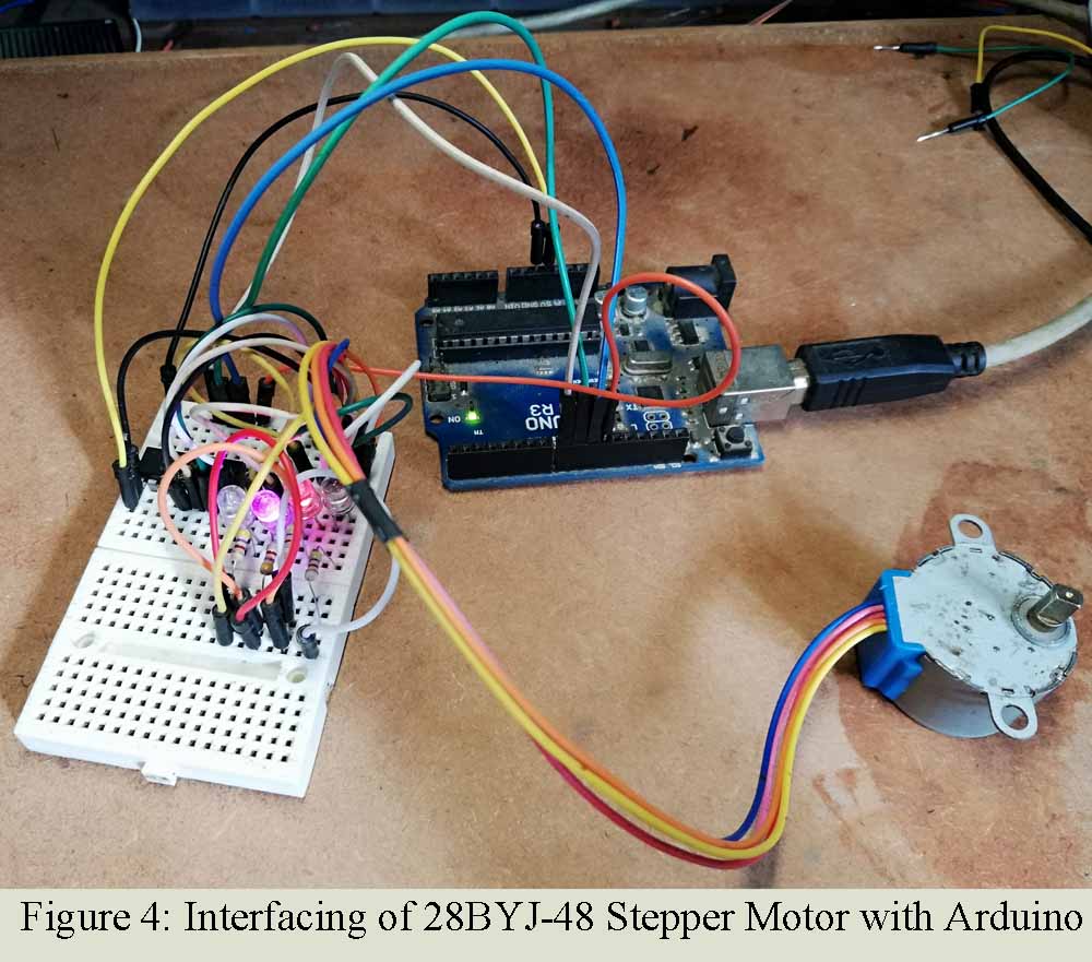
In this article we are going to interface unipolar and bipolar stepper motor and arduino using ULN2003 and L293D. The motor we are going to interface are MITSUMI M42SP-4NP stepping motor and 28BYJ-48 steeper motor
Introduction Stepping motor | Interfacing of Unipolar and Bipolar Stepper Motor with Arduino
An electric motor that rotates in a series of equal steps, each step controlled by a digital input signal, stepping motor are used in most electromechanical devices. Also called stepper motor. A stepper motor is an incremental motion machine i.e. the motor which turns in discrete movement (called the steps) is known as the stepper motor. Stepper motor does not rotate continuously as a conventional motor does.
Operation of stepper motor | Interfacing of Unipolar and Bipolar Stepper Motor with Arduino
The principle of operation of a stepper motor can be easily explained by considering a series of solenoids of electromagnetism arranged in a circle and an iron bar (rotor). When their solenoids are energized in sequence, the MMF developed in them interact with the iron bar (or rotor) and cause it to turn either in clockwise or counter-clockwise direction, depending upon the switching sequence.
IN this article we are controlling two stepper motor i.e. unipolar motor (28BYJ-48 stepper motor) and bipolar motor (MITSUMI M42SP-4NP).
Bipolar motor has two coils with four connectors where unipolar motor have four coils with five connectors. One end of each coil of unipolar motor is tied to VCC (say +5V) and other ends are taken out as shown in figure below. Before proceeding to circuit and programming lets identifies the pin of stepper motor.
Checkout other projects using stepper motor posted in bestengineeringprojects,com
Pin identification of stepper motor
There are two method of identification of pin of each coil
- Using LED: This method works with bipolar motors that have four wires, it is necessary to identify which wires corresponding to each of the coils. This is easy to do we need an LED with connector. All we have to do is to test the different wires to see if the LED lights up when we moved motor. When the LED does not light up even we move the motor, these two coils does not correspond to the same coil. Similarly, if the LED light up then the corresponding wire is of same coil.
- Using Multimeter: Check for continuity test of each wire. Following steps are used to identify the coils
- Adjust the multimeter in continuity mode.
- Check each connector corresponding to other connector.
- If the resistance between two connectors is low or multimeter start to beep, these two connectors are corresponding to same coil.
- If the resistance between two connectors is infinity, these two connectors are corresponding to same coil.
Circuit Description Interfacing of Unipolar and Bipolar Stepper Motor with Arduino
In this tutorial we are interfacing two different stepper motor thus we divide the description into two parts i.e. Unipolar Stepper motor interface with arduino and Bipolar stepper motor interfacing with arduino

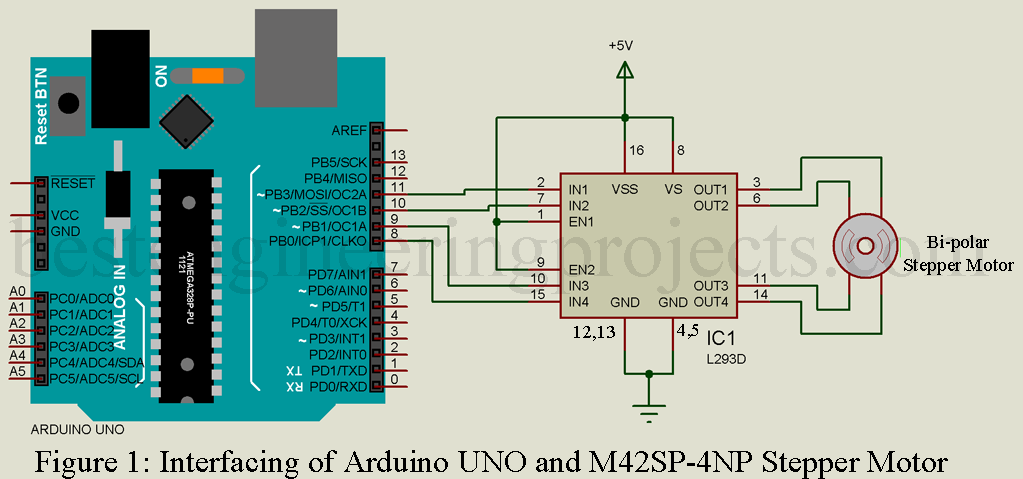
Bipolar Stepper Motor (MITSUMI M42SP-4NP) interface with arduino using L293D
The circuit of interfacing of bipolar stepper motor and arduino is shown in figure 1. This circuit is built around arduino uno and L293D. Four pin 4, 5, 12 and 13 is connected to ground where pin 1, 8, 9 and 16 is connected +5V supply of arduino. IN1, IN2, IN3 and IN4 is connected to arduino digital pin D11, D10, D9 and D8 respectively where output pin OUT1, OUT2, OUT3 and OUT4 are connected four of stepper motor as shown in figure 1.
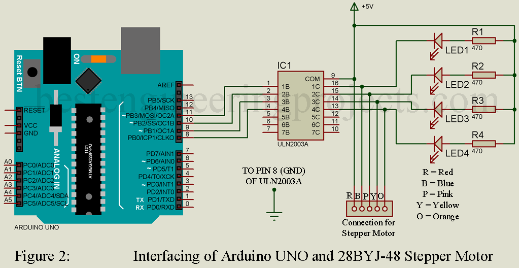
Unipolar Stepper motor (28BYJ-48) interface with arduino using ULN2003A
The circuit of interfacing of unipolar stepper motor and arduino is shown in figure 2. This circuit is built around arduino uno, ULN2003A, resistor and LED. ULN2003A is basically a Darlington Array IC and it consist seven NPN Darlington pair transistor capable of operating low voltage and low current motor. As it contains 7 NPN transistor thus 7 connector motor can be derived using this IC. Here we are driving unipolar stepper motor and it have four signal pin and a power supply pin. Thus, we need four arduino digital pin in order to drive this unipolar stepper motor.
The four-digital pin of arduino D11, D10, D9 and D8 is connected to 1B, 2B, 3B and 4B of IC ULN2003A respectively. The four-output pin of IC ULN2003A 1C, 2C, 3C and 4C are connected to one end of four coil of stepper motor as shown in above circuit diagram. Four LEDs are also connected to the pin of stepper motor through current limiting resistors. Pin 9 of IC ULN2003A is connected to common pin of coil.

Software Code: The software code of interfacing stepper motor with arduino is written in arduino programming language and compiled using arduino IDE.
|
1 2 3 4 5 6 7 8 9 10 11 12 13 14 15 16 17 18 19 20 21 22 23 24 25 26 27 28 29 30 31 32 33 34 35 36 37 38 39 40 41 42 |
/* Stepper Motor Control - one revolution This program drives a unipolar or bipolar stepper motor. The motor is attached to digital pins 8 - 11 of the Arduino. The motor should revolve one revolution in one direction, then one revolution in the other direction. Created 11 Mar. 2007 Modified 30 Nov. 2009 by Tom Igoe */ #include <Stepper.h> const int stepsPerRevolution = 200; // change this to fit the number of steps per revolution // for your motor // initialize the stepper library on pins 8 through 11: Stepper myStepper(stepsPerRevolution, 8, 9, 10, 11); void setup() { // set the speed at 60 rpm: myStepper.setSpeed(60); // initialize the serial port: Serial.begin(9600); } void loop() { // step one revolution in one direction: Serial.println("clockwise"); myStepper.step(stepsPerRevolution); delay(500); // step one revolution in the other direction: Serial.println("counterclockwise"); myStepper.step(-stepsPerRevolution); delay(500); } |
|
1 2 3 4 5 6 7 8 9 10 11 12 13 14 15 16 17 18 19 20 21 22 23 24 25 26 27 28 29 30 31 32 33 34 35 36 37 38 39 40 41 42 |
/* Stepper Motor Control - one step at a time This program drives a unipolar or bipolar stepper motor. The motor is attached to digital pins 8 - 11 of the Arduino. The motor will step one step at a time, very slowly. You can use this to test that you've got the four wires of your stepper wired to the correct pins. If wired correctly, all steps should be in the same direction. Use this also to count the number of steps per revolution of your motor, if you don't know it. Then plug that number into the oneRevolution example to see if you got it right. Created 30 Nov. 2009 by Tom Igoe */ #include <Stepper.h> const int stepsPerRevolution = 200; // change this to fit the number of steps per revolution // for your motor // initialize the stepper library on pins 8 through 11: Stepper myStepper(stepsPerRevolution, 8, 9, 10, 11); int stepCount = 0; // number of steps the motor has taken void setup() { // initialize the serial port: Serial.begin(9600); } void loop() { // step one step: myStepper.step(1); Serial.print("steps:"); Serial.println(stepCount); stepCount++; delay(500); } |
Note: Arduino code for both circuit is same and no need to modify.

