Sometimes, we must connect multiple LCDs to Arduino to display parameter readings or messages. In the tutorial “How to Interface Multiple I2C LCDs to Arduino,” you will learn how to interface multiple 16×2 I2C LCDs to your Arduino. After completing this tutorial, you will able to know:
- Select a different address for a 16×2 or 20 x 4 I2C LCD.
- How to interface multiple I2C LCDs with your Arduino?
How to select a different address for different 16×2 LCD
We have to configure some hardware to select the address of the I2C LCD. The I2C LCD driver we use here has solder pads labeled A0, A1, and A2, as shown in the figure below. As there are three solder pads, we can select 23 = 8 different address values between 0x20 and 0x27, as shown in the table below. Note: 0 represents open while 1 represents sorted.
By default, all the solder pads are disconnected (not sorted), and their default address is 0x27. Similarly, when all the solder pads are connected or sorted, their address becomes 0x20. All other addresses are between 0x27 and 0x20, as shown in Table 1.
| A2 | A1 | A0 | Hex Code |
| 0 | 0 | 0 | 0x27 |
| 0 | 0 | 1 | 0x26 |
| 0 | 1 | 0 | 0x25 |
| 0 | 1 | 1 | 0x24 |
| 1 | 0 | 0 | 0x23 |
| 1 | 0 | 1 | 0x22 |
| 1 | 1 | 0 | 0x21 |
| 1 | 1 | 1 | 0x20 |
In this way, you can select the address of each LCD.
How to interface I2C LCD to Arduino
To communicate between an I2C device and an Arduino, we need two pins, one for data and one for the clock. These pins are called SDA (Serial Data) and SCL (Serial Clock). In the case of Arduino UNO and Nano, pin A4 is SDA and pin A5 is SCL. The SDA pin of the device (LCD) is connected to the Arduino SDA pin (A4), while the SCL pin of the device (LCD) is connected to the Arduino SCL pin (A5), as shown in the circuit diagram.
Despite the data and clock pins, we need power rails for the power supply, i.e., +5V and GND. The VDD or VCC pin of the I2C device is connected to the +5V Arduino pin, and the GND pin of the I2C LCD is connected to the Arduino’s GND.
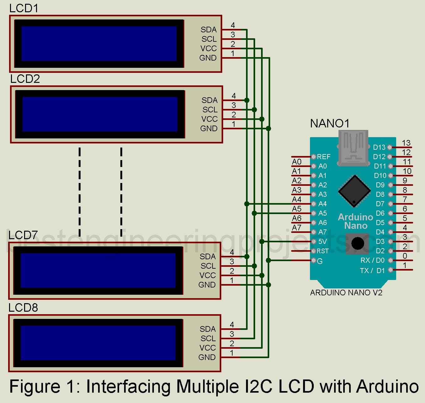
How to interface multiple I2C LCD to Arduino
The connection of multiple I2C LCDs is the same as that of a single I2C LCD, as shown in the circuit below. However, we must define each LCD’s corresponding address in the software code.
In this setup, you will use three I2C LCDs connected to an Arduino, but you can add up to 8 I2C LCDs. Here is a snapshot of each LCD:
20×4 LCD: This display can show up to 80 characters with configurations of 20 columns and 4 rows. I2C address: 0x27 This means this display will be identified through the said number via the I2C bus.
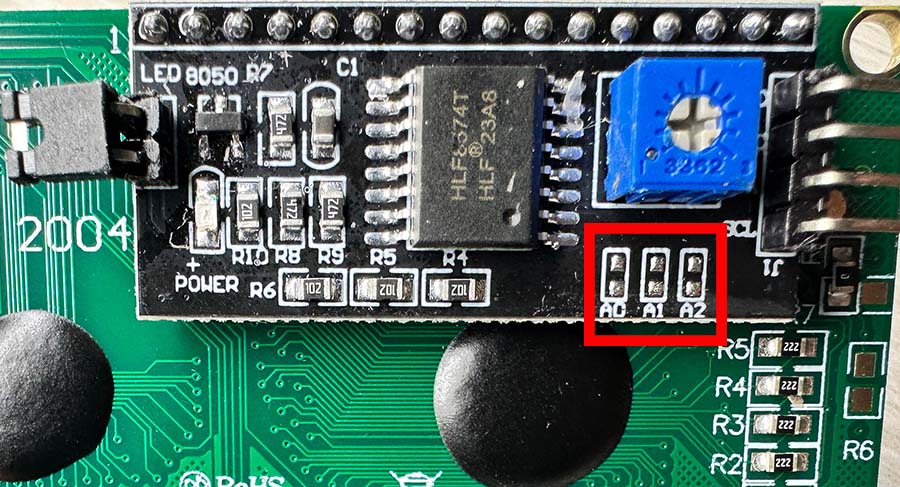 Figure 2: I2C LCD with Address 0x27
20×4 LCD: This one has 20 columns and 4 rows, like the previous one. Its I2C address is 0x25, distinguishing it from the other 20×4 LCDs.
 Figure 3: I2C LCD with Address 0x25
16×2 LCD: This display is small, with 16 columns and 2 rows and up to 32 characters on the screen at a time. The I2C address is 0x26.
 Figure 4: I2C LCD with Address 0x26
Software Code for Interface Multiple I2C LCD to Arduino:
|
1 2 3 4 5 6 7 8 9 10 11 12 13 14 15 16 17 18 19 20 21 22 23 24 25 26 27 28 29 30 31 32 33 34 35 36 37 38 39 |
#include <Wire.h> #include <LiquidCrystal_I2C.h> // Initialize LCD objects for different addresses and sizes LiquidCrystal_I2C lcd1(0x27, 20, 4); // 20x4 LCD with address 0x27 LiquidCrystal_I2C lcd2(0x26, 16, 2); // 16x2 LCD with address 0x26 LiquidCrystal_I2C lcd3(0x25, 20, 4); // 20x4 LCD with address 0x25 void setup() { // Initialize each LCD lcd1.init(); lcd2.init(); lcd3.init(); // Turn on backlight for all LCDs lcd1.backlight(); lcd2.backlight(); lcd3.backlight(); // Display the address on each respective LCD lcd1.setCursor(0, 0); lcd1.print("LCD Address:"); lcd1.setCursor(0, 1); lcd1.print("0x27"); lcd2.setCursor(0, 0); lcd2.print("LCD Address:"); lcd2.setCursor(0, 1); lcd2.print("0x26"); lcd3.setCursor(0, 0); lcd3.print("LCD Address:"); lcd3.setCursor(0, 1); lcd3.print("0x25"); } void loop() { // Nothing to do in the loop } |
The code creates three LiquidCrystal_I2C objects called lcd1, lcd2, and lcd3, with each one representing a different LCD display:
- lcd1 is a 20×4 LCD, and its I2C address is set to 0x27.
- lcd2 is a smaller 16×2 LCD, and its I2C address is 0x26.
- lcd3 is another 20×4 LCD, with its I2C address as 0x25.
For initialization, the code uses lcd1.init(), lcd2.init(), and lcd3.init() to set up each LCD and establish communication, preparing them to display data.
To turn on the backlight for each LCD, the code calls lcd1.backlight(), lcd2.backlight(), and lcd3.backlight(). The backlight makes the displays easy to read in various lighting conditions.
Each LCD is configured to display its I2C address on its screen. All the initialization and the display of relevant messages are done in the setup() function; the loop() function is empty since nothing more needs to be done after setup.
This setup can be used simply to identify and verify that each I2C LCD is properly connected and working as expected.
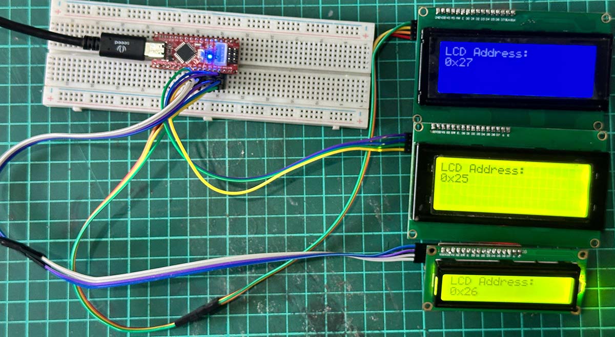 Figure 5: Author Prototype for Interfacing Multiple I2C LCD with Arduino
To configure multiple non-I2C LCDs with Arduino, you can use multiplexing to share standard data lines among multiple displays. In a 4-bit data mode, the higher data pins (D4-D7) of all LCDs connect to Arduino pins, while the RS and Enable pins are connected to separate Arduino pins for each display. This lets you send different data to each LCD using the LiquidCrystal library. Refer to this article on Best Engineering Projects (Engineering Projects) for a complete guide and example code.