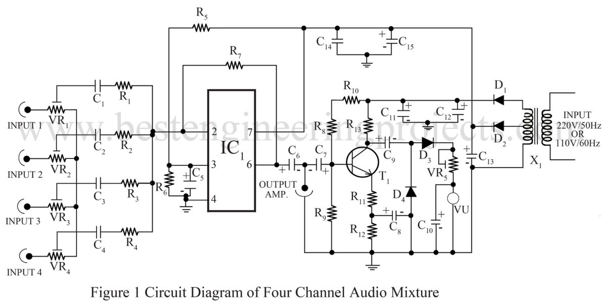
As per the name of the circuit, it is clear that this circuit connects four different audio signals as one. So, it is call four channel audio mixer. Here is that simple circuit; “four channel audio mixer” using op-amplifier 741. It is to be noted in the circuit that the op-amplifier 741 works here as an inverting amplifier.
Circuit Description of four channel audio mixer:
The circuit of four channel audio mixer is wired around op-amp IC 741 followed by few other active as well as passive components. The IC 741 as previously mentioned works in inverting mode with extra resistor for every single input channel. When a single audio signal is fed as input in the circuit, it starts working as an inverting amplifier, where R1 and R7 are combined for voltage gain. Capacitor C1 behaves as a blocking capacitor whereas variable resistor VR1 as signal controller for channel 1.
In the circuit four channel audio mixer, when two or more audio signals are fed in the input terminal, then the input circuit combines all input signals as one and connects the input pin of audio signals with inverting pin of the IC-741. As a result, the voltage in the output pin is equal to the total sum of every individual input signal.
This circuit is used as a high quality audio mixer.
For stereo effect, two different circuits can be used to obtain the desired output.
NOTE:
We have tested four channel audio mixture in lab of BEP with three different input signals.
Check out the other audio mixture circuit posted in bestengineeringprojects.com
PARTS LIST OF FOUR CHANNEL AUDIO MIXTURE
|
Resistor (all ¼-watt, ± 5% Carbon) |
|
R1 – R4, R7 = 100 KΩ R5, R6 = 39 KΩ R8 = 220 KΩ R9, R10 = 22 KΩ R11 = 150 KΩ R12 = 330 KΩ R13 = 4.7 KΩ VR1 – VR4 = 100 KΩ VR5 = 1 KΩ |
|
Capacitors |
|
C1 – C4 = 0.22 µF (Ceramic Disc) C5 = 100 µF/12V (Electrolytic capacitor) C6, C7 = 10 µF/16V (Electrolytic capacitor) C8, C10, C12, C15 = 100 µF/25V (Electrolytic capacitor) C9 = 10 µF/25V (Electrolytic capacitor) C11, C13 = 2000 µF/25V (Electrolytic capacitor) C14 = 100 KpF (Ceramic Disc) |
|
Semiconductors |
|
IC1 = 741 (operational amplifier) T1 = BC148B (NPN transistor) D1 – D4 = 1N4001 (rectifier diode) |
|
Miscellaneous |
|
X1 = 220V/50 Hz or 110V/60Hz primary to 9V – 0 – 9V secondary step down centre tap transformer |

Does c 14 and c 15 make power supply regulate ??.
Why you used RC in 3 and 4 input.??
Please guide me.
Capacitors C14 and C15 is act as filter to reduce ripple voltage available at output of rectifier.
The circuit posted here is of four channel audio mixture, and can mix up-to four different input.All inputs (including 3 and 4) need RC circuit because series resistor in each channel is to keep the op-amp from functioning like a differentiator and capacitor is used to block DC signal if any available in audio source.
Hello sir. May i ask a question? What is that VU in the schematic diagram? And what is the amperage of the transformer in the circuit? I hope to get response from you. Thanks alot!
VU stand for Volume Meter or you can also say standard volume indicator for representation of audio signal level.
transformer of 750mA or 1A is preferable.
Thanks alot sir!
Hello sir. I’m planning to use this project. I just wan’t to ask the amperage of the 9-0-9 transformer and I’m wondering, what is that VU in the schematic diagram? Thanks in advance!
Hello sir. What is the advisable amperage for the transformer? And another thing can I use BC548 transistor instead of BC148B?
Transformer of 750mA or 1A rating is preferable.
You can go with 2N2222 or BC107.
Thank you ??
Hello sir another question. Can you give me some advice of what kind or what voltage of dc speaker can I use to have it built in with my audio mixer. Thank you
The output of this circuit is given to the power amplifier for further amplification. If you directly connect speaker the sound would be very low or noisy.
Hello again sir. We used the circuit and thanks it works but the problem is the sound it produces in the output when connected to a speaker is really low. Is there a problm in the circuit or do we need to put an audio amplifier circuit to it? Thanks again.
Use Power amplifier for proper output.
This will be a big help. Thank you again sir! :)
hello, sir! i think I did all connections to the circuit and use 9-0-9 750mA transformer and a 2n2222A transistor instead (as recommended). I should ask what’s the problem with my work that it’s not functioning. Could you suggest the common mistakes that I might did in doing this circuit? Big thanks!
Check all the connection once more and use proper amplifier circuit because the circuit posted above need amplification in order to drive loudspeaker.
Hello again sir! Can i directly put dynamic microphone into the input. If not, can you please give me suggestions on how to make pre amp for dynamic microphone input that i can cascade to this circuit. Thanks in advance sir!
Ok, we will design a circuit of dynamic microphone pre-amp circuit. Flow up this website for more information.
Thankyou sir! I will wait for the circuit that you will make. Thanks alot again :)
Hello sir. Do you have any circuit of a Variable Sinewave Generator using op amp and a dc supply (12v or 9v) in which we can adjust its frequency using potentiometer
This post might help you.
http://bestengineeringprojects.com/low-frequency-sine-wave-synthesizer/
Thank you sir