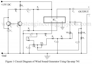
Various sound generator projects is already posted in bestengineeringprojects.com in alarm and sound generator section. Now here is one another sound generator circuit using most popular and versatile operational amplifier IC 741. The circuit posted here is of wind sound generator using IC 741 produces wind sound. Circuit Description of Wind Sound Generator Using IC 741 The circuit of wind sound generator comprise operational amplifier 741, two NPN transistors (BC148) and some passive components (resistors and capacitors). Transistors T1 and T2 generate wind sound. A jumper is connected to emitter…
Read MoreCategory: Electronics Projects
DC Volt Polarity Indicator Using IC 741
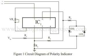
Now, here is another basic electronic project using the most versatile operational amplifier IC 741 “DC Volt Polarity Indicator”. Using the project DC volt polarity indicator one can know the positive and negative polarity of DC volt. This project is very useful for electronics hobbyists to check either battery polarity or polarity at the output of the DC source. The circuit present here is so simple that even electronics beginners can understand how the circuit works. Circuit Description of DC Volt Indicator Using IC 741 The heart of the circuit…
Read MoreMulti Tone Generator Circuit
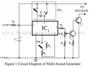
Here one another sound generator project is added is section of alarm and sound generator projects. We have tested and posted dozens of sound or tone generator projects. Now, here is multi-tone generator circuit which produces eight different types of tones. The tones produced by the circuit multi tone generator are of Bell, Ambulance Siren, Whistle, Machine gun Sound, Jingle, Police siren, Birds and Dual sound. Circuit Description of Multi Tone Generator Circuit The heart of the circuit multi tone generator is UM5561 IC (IC1) and the entire circuit is…
Read MoreOperational Amplifier 741 Tester
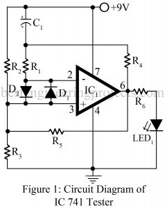
The op-amp IC 741 is a DC-coupled, high gain differential amplifier with external negative feedback. IC 741 is characterized by the almost infinite open-loop gain (100,000), almost infinite input impedance (2MΩ), and almost zero output impedance (75Ω). IC 741 is the most popular, cheap, and easy-to-use op-amp. Various type of circuit is designed using Op-amp 741 out of which some are voltage follower, current to voltage converter and vice versa, summing amplifier, etc. Various type of circuit based on op-amp 741 is already posted in bestengineeringprojects.com on the op-amp section.…
Read MoreFlasher Circuit
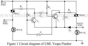
Replacement of burnt LML vespa flasher costs around $ 2.5. The flasher can be replaced with the help of the circuit sows here. It costs around $1.2. Circuit Description of LML Vespa Flasher The circuit of LML vespa flasher consists of a multivibrator built around transistors T1 and T2. The time period of the pulse can be varied by changing the values of R1, R2, C1 and C2. The values shows in the circuit are chosen to match the flasher with the flashers available in the market. Gates of TRIAC…
Read MoreMains Supply Interruption Indicator Circuit
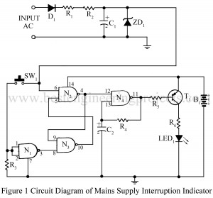
The Mains Supply interruption indicator circuit can be used in applications where it is necessary to know whether the mains supply has been continuous or not. The circuit mains supply interruption indicator will be useful for monitoring mains supplies to recording equipment, especially in the recording of computer software tapes, where the slightest interruption in the mains supply will cause an error in the data being recorded. It can also be used with digital clocks working on mains. An interruption in the mains supply will cause an LED to flash…
Read MoreVariable Switching Power Supply
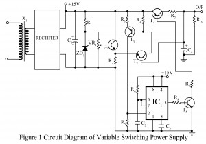
Various type of power supply circuit from basic regulated power supply to advanced digital control power supply unit is already posted on bestengineeringprojects.com. Now here one more power supply circuit is posted and can be used to provide up to 300mA and voltage between 6V to 13V. Circuit Description of Variable Switching Power Supply The input AC is stepped down using a step-down transformer T1 to 18V AC which is further rectified by a bridge rectifier. The rectified output is filtered by 1000 capacitor C1. The Zener diode ZD1 is…
Read MoreLow Power Alarm with Automatic Timer
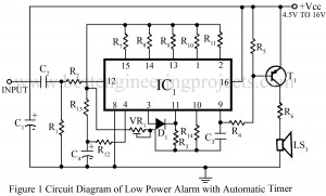
Various types of alarm and sound generator circuit is already published in bestengineeringprojects.com. Now here is a alarm circuit which draws very low quiescent current and also does not need any type of power on off switch because this offers automatic switch-off after fixed time. Circuit Description of Low Power Alarm with Automatic Timer The heart of the circuit low power alarm circuit is 4060 IC, which is here configured as timer. The advantage of using IC 4060 (IC1) is the wide music range instead of UM series musical IC.…
Read MoreSmallest Radio Circuit Using Two Transistors
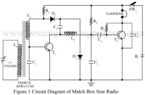
This small-size radio published is very interesting and useful for students. Using the circuit Smallest Radio Circuit Using Two Transistors described here, one can make a very compact MW radio receiver. This circuit uses only two transistors and a few passive components, as all the components can be easily placed in a small matchbox-size cabinet. Smallest Radio Circuit Using Two Transistors Coil L1 consists of 100 turns of 40 SWG insulated wire. Wind L2 over L1, which is 10 turns of the same wire. For L3, wind 56 SWG (approximately)…
Read MoreMains box heat monitor using 555 Timer IC
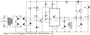
Here is a simple circuit mains box heat monitor for sensing high temperature due to overheating. This circuit helps to prevent disasters caused by only sparking in the mains box due to any fault as a short circuit overloaded. This circuit is so designed that it also automatically switches on a bright white LED (LED3) in case of power failure. This light is sufficient to check the mains box wring or fuses in darkness. Circuit Description Mains Box Heat Monitor The circuit is built around a timer IC, a sensor,…
Read More