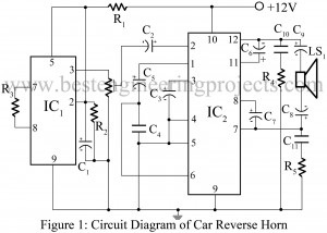
Unexpected incidents occur in the road when the driver is unaware about certain activities that may lead to accidents in the vicinity. For instance, suppose you are on a trip with your family and driving along the narrow road, while you were in the middle of conversation, you notice car right at the front is driving backwards towards your car and in seconds is going to hit you. It may be too late before you realize the situation. Maybe if you had known earlier, you could save yourself and your…
Read MoreCategory: Electronics Projects
Telephone Amplifier Circuit
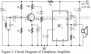
Telephone talks are meant to be private or kept in between two persons engaged in the conversation. But, sometimes it is also necessary to have a group talk. The project entitled Telephone amplifier circuit serves us right. It is very simple, yet inexpensive and useful which uses very common power amplifier LM386 and some more components. The circuit can be used to produce loud sound to discuss or start a conversation in a group through telephone. Working of the Telephone Amplifier Circuit The signal emitted as output from telephone is…
Read MoreMulti Sound Generator Circuit
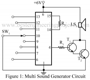
Sound generating circuits fascinates everyone. Dedicated circuits are available in the market to provide a single type of sound or technically it can be said as ‘circuits with one level of intensity of sound’. In contrast to those circuits, here we present you a multi-sound generator circuit which offers a wide range of sound intensities as directed by the name of project itself. The multi sound generator circuit is designed such that it produces a total of eight different levels/types of sound from the single circuit. This is what makes…
Read MoreElectronic Siren Circuit
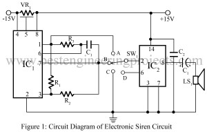
Multiple alarm circuits are developed and are distributed in the market so as to serve the needs and demands of client. Though the design parameter may vary, but all circuits are based on the same principle to provide security services under probable conditions. Designing these circuits becomes entertaining with different sound effects we can use during the designing phase. A similar electronic siren circuit is depicted in the figure below. The electronic siren circuit is different from other siren circuits from a fact that it uses a dual-amp MC1458,…
Read MoreBattery Saver Circuit
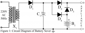
“Dry cell is not rechargeable”, this is what people think. This concept can be proven wrong by this particular project ‘Dry cell charger‘. Now here is another electronics trick to make the concept of ‘Battery Saver’ come true. The project battery sever not only charges dry cell but also enhances battery life by saving energy. The project ‘Battery saver circuit’ is considered very useful project for those, who run their appliance solely based on dry cell. Circuit Description Batter Saver Circuit:- The circuit is so simple that anyone can understand,…
Read MoreSimple Touch Switch Using Two Transistor
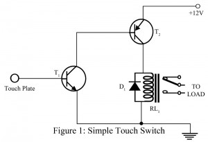
The project shown here is of simple touch switch circuit using two transistor which is used to control various types of electrical appliances like electrical bulb, fan, door bell etc. The complete circuit is build around two general purpose transistors, a relay and a touch plate. The length of wire connected between touch plate and base of transistor T1 must be short as possible, where size of touch plate must not exceed the size of 1 rupee coin. Transistor T1 is used as signal amplifier where T2 is a relay…
Read More555 Timer IC Tester
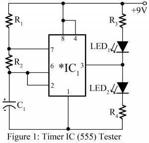
NE555 Timer IC is very popular and one of the most commonly used components in electronics circuits. NE555 Timer IC is also called Ideal IC since it offers multiple features like multipurpose functionality, low power consumption, small size, and durability. When we work on a particular project and it doesn’t work the way we wanted, before the circuit we doubt whether the IC used, is working or not. More or less, blaming IC is reasonable since IC is the combination of many more components or IC itself is a combination…
Read MoreDry Cell Charger | Easy Electronic Projects
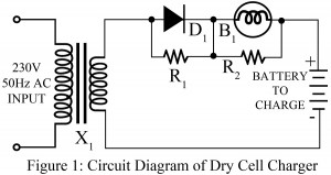
We all are fed with the fact that dry cell is not rechargeable and it has no use once it is discharged during use. And, people simply throw it away and buy a new one. Because of this, people are forced to invest quite a lot on battery. In order to overcome this problem, here we have presented a new project ‘Dry Cell Charger’, which has been tested and verified practically. Using the circuit dry cell charger one can charge dry cell 6 to 8 times which evidently contributes to…
Read MoreElectronics Cricket Project | Game Circuit
Indoor games play a vital role in our busy schedule where we can’t spare time to refresh ourselves and enjoy game on the ground. In city areas, lack of playground can be a greater obstacle. The circuit electronic cricket project solves all problem, it is very interesting project not only for those who love cricket but for also those people who love to watch this game. The game electronic cricket can be played by anyone, even in their home by sitting on table or at the corner of a room,…
Read MoreWoofer Tweeter Crossover
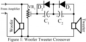
When using speakers, people must have faced quite a lot of problems due to failure of the speaker to produce smooth sound quality continuously. It is because speaker detects only identical frequency and does not give response to all frequency. Particular range of low frequencies is detected by the speaker and it ignores high frequencies. Woofer or tweeter is introduced as a solution to this issue. However, if the signal from amplifier is directly fed to woofer or tweeter, then it may not produce the actual sound. And, a crossover…
Read More